An ultra-thin heat pipe

A technology of ultra-thin heat pipe and heat insulation section, which is applied in the direction of indirect heat exchangers, lighting and heating equipment, semiconductor devices, etc., and can solve the lack of synergistic optimization of heat transfer and flow resistance, fluid flow, heat transport restrictions, and working fluid flow To solve problems such as large resistance, achieve the best cost performance, improve field synergy, and overcome the effect of large flow resistance

Active Publication Date: 2019-08-23
南京艾科美热能科技有限公司
View PDF3 Cites 0 Cited by
  • Summary
  • Abstract
  • Description
  • Claims
  • Application Information

AI Technical Summary

Problems solved by technology

However, due to the ultra-thin nature of the ultra-thin heat pipe, the fluid flow and heat transport are restricted, which limits its heat transfer performance.
It is mainly manifested in the large flow resistance of the working liquid, the small space for steam circulation, and the weak capillary driving force, especially the lack of synergistic optimization of capillary phase change heat transfer and flow resistance, which leads to the inability to quickly diffuse heat, the decrease of the maximum heat transfer capacity and the thermal resistance. larger

Method used


Image

  • An ultra-thin heat pipe
  • An ultra-thin heat pipe
  • An ultra-thin heat pipe

Examples


Embodiment Construction

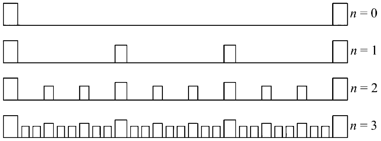
[0035] In order to solve the problems of large internal working medium flow resistance and limited maximum heat transfer capacity of existing ultra-thin heat pipes, the present invention provides a novel ultra-thin heat pipe with fractal stepped capillary core structure. The following describes the present invention in conjunction with the drawings and examples Further details. It should be understood that the specific embodiments described here are only used to explain the present invention, not to limit the present invention.

[0036] A further detailed description is carried out below in conjunction with the description of the accompanying drawings:

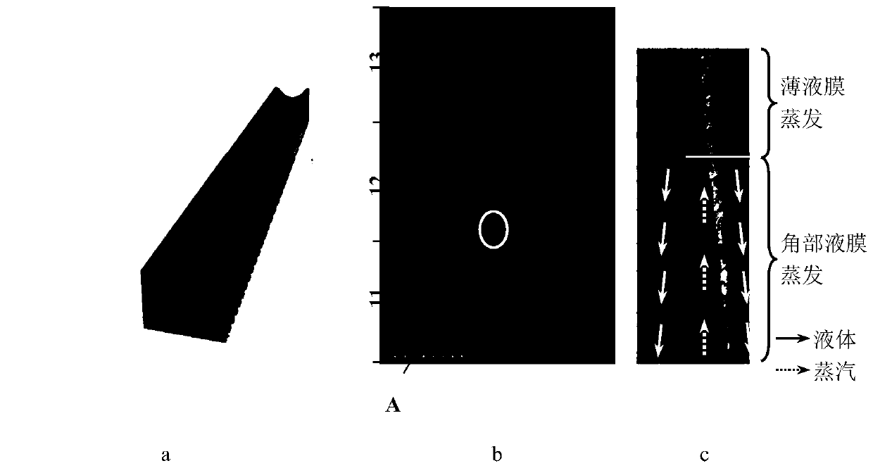
[0037] The invention relates to an ultra-thin heat pipe, which comprises a shell, a steam cavity and a capillary core. The inner space of the shell is a steam cavity, and the capillary core is arranged inside the shell. The ultra-thin heat pipe is provided with a condensing surface, an evaporating surface and an adiabatic sur...


PUM


Abstract

The invention discloses an ultra-thin heat pipe which comprises a shell, a steam cavity and a porous wick; a working medium is filled in the steam cavity; the ultra-thin heat pipe is provided with a condensation section, an evaporation section and a heat insulation section; the porous wicks include fractal cascade porous wicks and sparse porous wicks; the fractal cascade porous wicks are arrangedon the inner walls of the evaporation section and the condensation section; the sparse porous wicks are arranged on the inner wall of the heat insulation surface; and the fractal cascade porous wicksare formed by arranging m fractal cascade micro-groove units which are arranged on the shell in parallel. By arranging the fractal cascade porous wicks, the ultra-thin heat pipe provided by the invention has the advantages of strong capillary force, low flow resistance and large heat transfer capacity, can efficiently lower the temperature of a local heat source and improves the working reliability and the stability of a microelectronic device.

Description

technical field [0001] The invention relates to the field of heat dissipation of electronic equipment, in particular to an ultra-thin heat pipe applied to heat dissipation of microelectronic devices in a confined space. Background technique [0002] Moore's Law states that the performance of electronic products doubles every 18 months. Therefore, the power consumption of the chip must increase accordingly, and the heat consumption generated is also increasing. At the same time, with the development of micro-electronic machinery, more and more electronic components are packaged in tiny spaces. This has resulted in increasing heat consumption of electronic devices, but the package size is getting smaller and smaller, so the heat flux density per unit area and unit volume is getting higher and higher. Research and practical applications show that 55% of electronic equipment failures are caused by overheating, and the reliability of the system will decrease by 50% for every 10...

Claims


Application Information

Patent Timeline
Patent Type & Authority Patents(China)
IPC IPC(8): F28D15/04H01L23/427
Inventor 徐德好
Owner 南京艾科美热能科技有限公司
Why Eureka
Try Eureka