Flat curved type heat pipe integrated heat radiator for electron element
A technology that integrates heat sinks and electronic components. It is applied in electrical components, electrical solid devices, indirect heat exchangers, etc. It can solve problems such as affecting heat dissipation, and achieve the effect of large contact area, large heat dissipation, and reduced thermal resistance.
- Summary
- Abstract
- Description
- Claims
- Application Information
AI Technical Summary
Problems solved by technology
Method used
Image

Examples
Embodiment 1
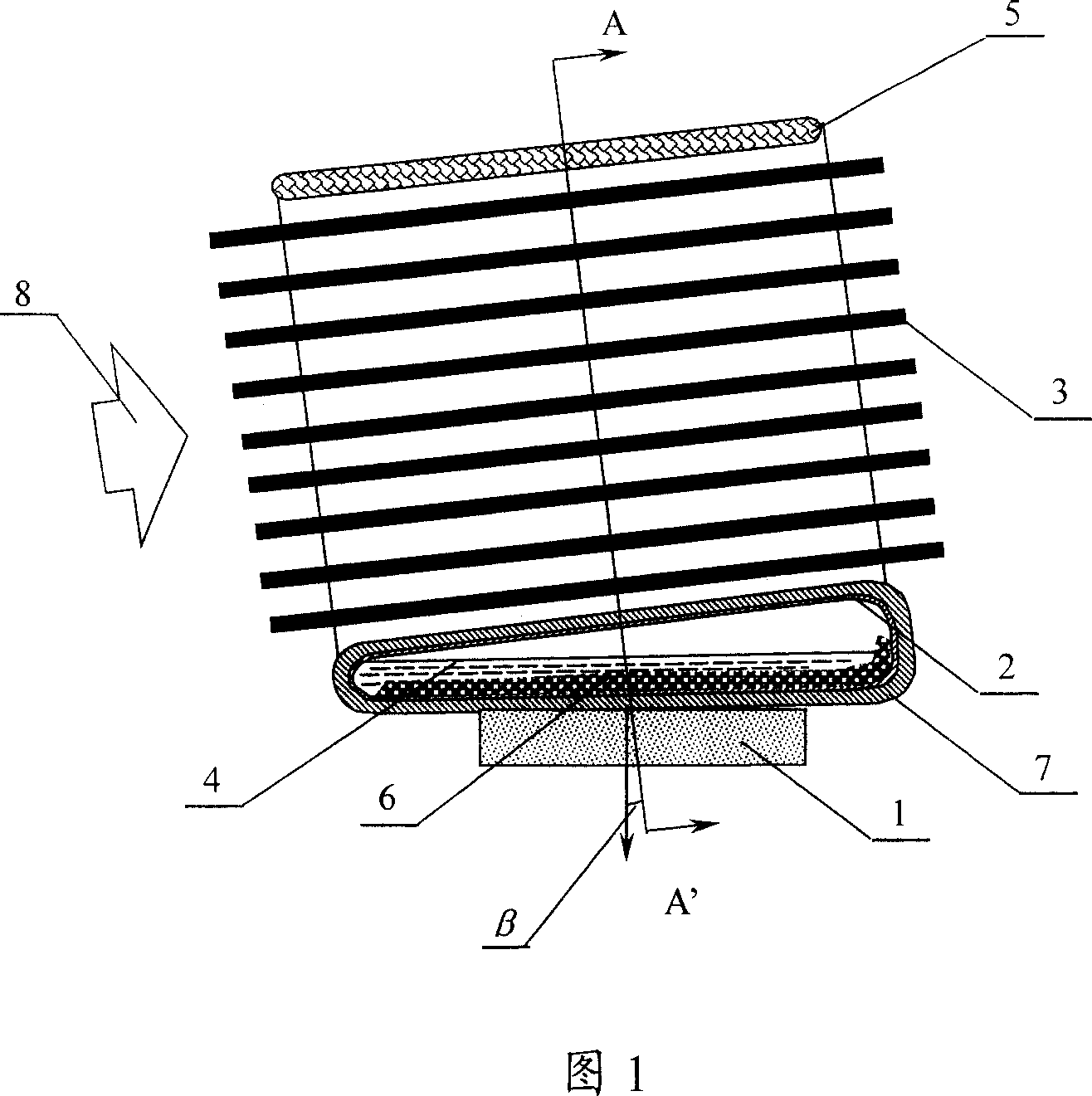
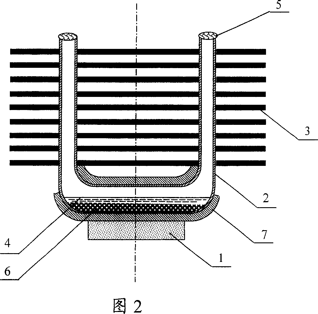
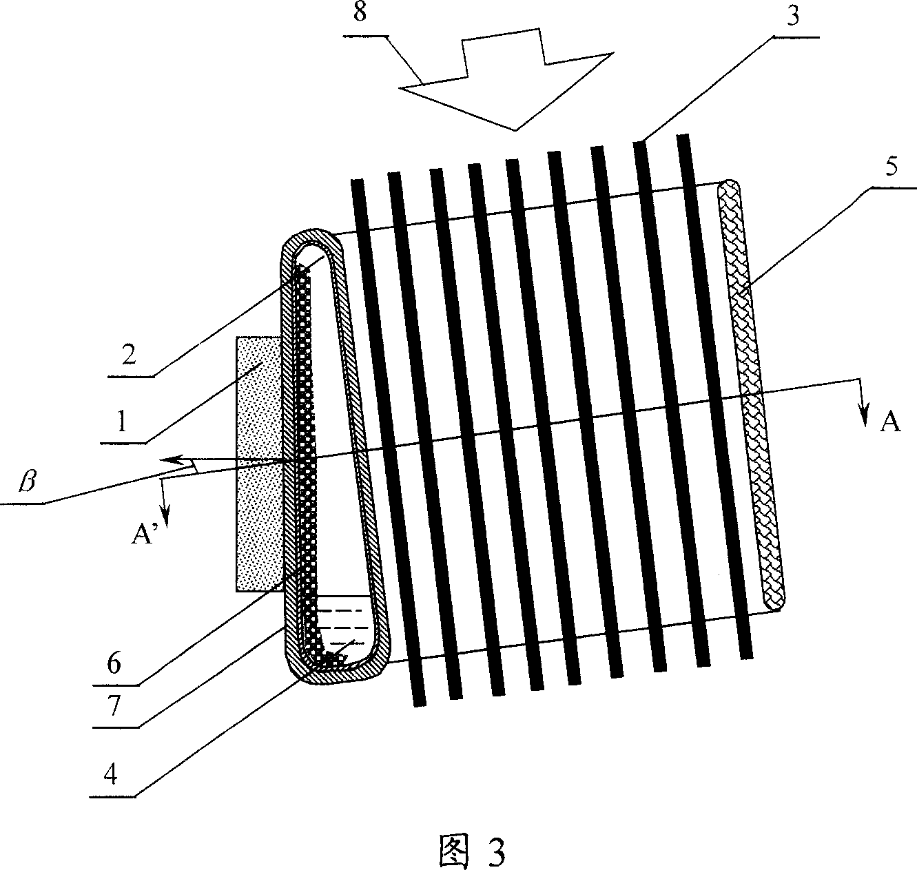
[0021] Manufacture the integrated radiator in the form of Figures 1, 2, and 3. A rectangular copper tube with a wall thickness of 0.5mm and a cross-sectional size of 40×5mm, with a length of 150mm, is bent into a U-shaped tube blank with a middle distance of 40mm and a height of 50mm according to Figure 2. Put the tube blank into the mold for hydroelectric forming, and shape it into a U-shaped flat tube 2. The straight section of the U-shaped tube becomes a flat ring shape of 45×5mm, and the contact with the electronic component 1 becomes 45mm wide. One side is 5mm, one side is a 7mm drop-shaped section (aspect ratio of 45 / 7=6.43), and the straight section of the U-shaped tube forms an angle of 2.8° with the normal direction of the bottom surface. Put 3~5g 100(mesh copper powder in the heating part of the U tube, cover both sides with 1.5mm reinforcing copper sheet 7, and then punch the punched 0.3mm thick copper fin 3, and clamp it at a distance of 0.5~0.8mm Install it on th...
Embodiment 2
[0023]Manufacture the integrated radiator in the form of Figures 1, 2, and 3. A rectangular copper pipe with a wall thickness of 0.5mm and a cross-sectional size of 20×5mm, with a length of 150mm, is bent into a U-shaped pipe blank with a middle distance of 40mm and a height of 50mm according to Figure 2. Put the tube blank into the mold for hydroelectric forming, and shape it into a U-shaped flat tube 2. The straight section of the U-shaped tube becomes a flat ring shape of 25×5mm, and the contact with the electronic component 1 becomes 25mm wide. One side is 5mm, one side is a 7mm drop-shaped section (aspect ratio of 25 / 7=3.57), and the straight section of the U-shaped tube forms an angle of 4.6° with the normal direction of the bottom surface. Put 3-5g of 100-mesh copper powder into the heating part of the U tube, cover both sides with 1.5mm reinforcing copper sheet 7, coat silver-copper solder on all parts to be welded, put it into a vacuum furnace, and heat it at 800-850°...
Embodiment 3
[0025] Manufacture the integrated radiator in the form of Figures 4 and 5. Take a rectangular copper tube with a wall thickness of 1mm and a cross-sectional size of 25×5mm, and a length of 300mm. According to Figure 4, bend it into a coil blank with a middle spacing of 30mm, an outer spacing of 25mm, and a height of 50mm. Seal one end of the coiled tube, and connect the other end with a pressure tube, put it into the mold and add 40MPa of water pressure to shape it into a flat coiled tube 2. ×8mm rectangular section (aspect ratio of 26 / 8=3.25); put 3~5g of 100 mesh copper powder into the heating part of the snake tube, and then punch the punched 0.3mm thick copper fin 3, press 0.5~ 0.8mm spacing is clamped on the snake tube, silver-copper solder is coated on the part to be welded, placed in a vacuum furnace, and the brazing fins are heated at 800-850°C and copper powder is sintered; both ends of the copper tube are sealed and soldered, and the soldering liquid is returned Pip...
PUM
 Abstract
Description
Claims
Application Information
 - R&D
- Intellectual Property
- Life Sciences
- Materials
- Tech Scout
- Unparalleled Data Quality
- Higher Quality Content
- 60% Fewer Hallucinations
Browse by: Latest US Patents, China's latest patents, Technical Efficacy Thesaurus, Application Domain, Technology Topic, Popular Technical Reports.
© 2025 PatSnap. All rights reserved.Legal|Privacy policy|Modern Slavery Act Transparency Statement|Sitemap|About US| Contact US: help@patsnap.com