


Quick Research
Generate reliable direction feasibility study reports for your R&D in just a few steps.

Technical Q&A
Discover and master advanced knowledge NOW. Basics, ideas, possibilities, all at once.

Find Solutions
As an expert in R&D theories, this can generate solutions to your technical problems instantly.

Evaluate Feasibility
Analyze your overall solution with one click, know your potential R&D risks in advance.

Monitor Landscape
Get weekly tech updates, stay abreast of the latest tech innovations and key insights.
Direction-adjustable ratchet wheel type self-locking movable joint
A kind of flexible joint, self-locking technology, applied in excavation, construction, infrastructure engineering and other directions, can solve the problems of flexible joints can only withstand pressure, inconvenient installation and disassembly of flexible joints, easy corrosion of stressed parts, etc., to prevent excessive deformation. , the effect of strengthening the integrity, increasing the bearing capacity and stiffness
- Summary
- Abstract
- Description
- Claims
- Application Information
AI Technical Summary
Problems solved by technology
Method used
Image

Examples
Embodiment 1
[0069] In an optional solution of this embodiment, this embodiment provides an adjustable ratchet type self-locking joint, including a movable end, a fixed end and an adjustable ratchet mechanism.
[0070] In this embodiment, the articulating joint can only withstand pressure.
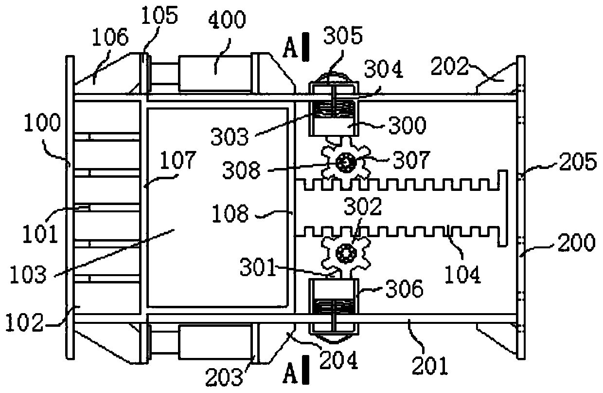
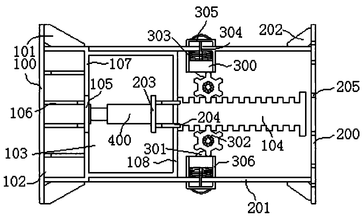
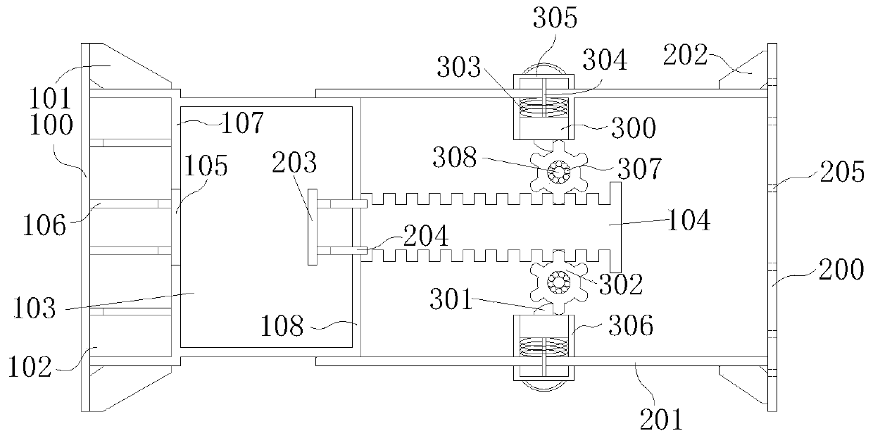
[0071] Such as figure 1 As shown, the movable end includes movable end flange 100, movable end rib 101, movable end steel pipe 102, movable end embedded steel pipe 103, rack 104, movable end flange 105, movable end flange stiffener 106, movable end Steel pipe sealing plate 107 and embedded steel pipe sealing plate 108; fixed end includes fixed end flange 200, fixed end steel pipe 201, fixed end rib 202, fixed end wing plate 203 and fixed end wing plate stiffener 204; adjustable ratchet The mechanism includes a ratchet 300 , a ratchet bar 301 , a ratchet 302 , a spring 303 , a connecting rod 304 , a steering handle 305 , a ratchet steel pipe 306 , a ball 307 and an axle 308 .
[0072] In this embodime...
Embodiment 2
[0081] In this embodiment, the flexible joint can withstand both tension and compression.
[0082] In the optional solution of this embodiment, it is partly different from Embodiment 1 in that, when the erection is nearing completion, after the jack 400 reaches the predetermined elongation length, do not immediately return the oil to remove the jack 400, but keep the jack 400 unloaded and leave it. At the original position, select a group of relative adjustable ratchet mechanisms, lift the steering handle 305, rotate the steering handle (305) 180°, and then relax the steering handle 305. Then, at this time, the straight surface of half of the spines 301 faces the movable end, which limits the extension of the movable end, and the straight surface of the other half of the spines 301 faces the fixed end, which limits the retraction of the movable joint. At this time, the jack 400 can be removed. , the entire erection is complete. Use process such as image 3 , 5 As shown, the...
PUM
 Abstract
Description
Claims
Application Information
 - R&D Engineer
- R&D Manager
- IP Professional
- Industry Leading Data Capabilities
- Powerful AI technology
- Patent DNA Extraction
Browse by: Latest US Patents, China's latest patents, Technical Efficacy Thesaurus, Application Domain, Technology Topic, Popular Technical Reports.
© 2024 PatSnap. All rights reserved.Legal|Privacy policy|Modern Slavery Act Transparency Statement|Sitemap|About US| Contact US: help@patsnap.com