
Design method of tubular part spin forming spinning roller tracks

A technology of spinning forming and trajectory design, which is applied in computing, special data processing applications, instruments, etc., to achieve the effect of improving production efficiency and shortening forming time

Active Publication Date: 2019-05-10
NINGBO UNIV
View PDF4 Cites 12 Cited by
  • Summary
  • Abstract
  • Description
  • Claims
  • Application Information

AI Technical Summary

Problems solved by technology

However, there are still defects in this construction method. Since the roller returns to the original starting point after the first pass of forming, the first profiling is performed at this time, but there is actually a gap between the roller and the blank, so the roller will be lost during the profiling. There is a period of empty knife time, and multi-pass empty knife will greatly increase the production time of a part. For this reason, it is necessary to optimize the track of the rotary wheel to compensate for this gap

Method used


Image

  • Design method of tubular part spin forming spinning roller tracks
  • Design method of tubular part spin forming spinning roller tracks
  • Design method of tubular part spin forming spinning roller tracks

Examples


Embodiment Construction

[0031] The present invention will be further described below in conjunction with the accompanying drawings and specific embodiments.

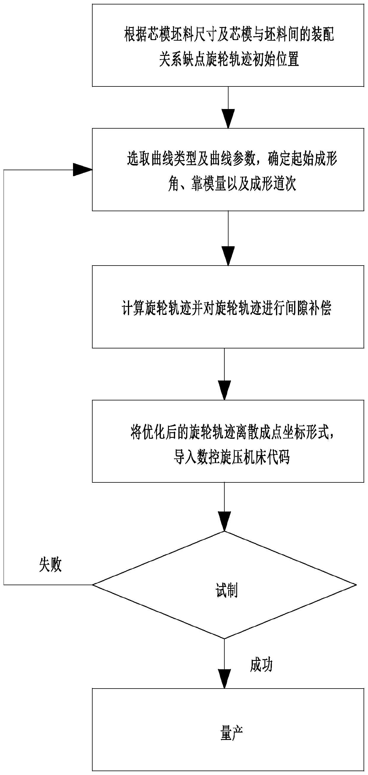
[0032] The blank 9 in this embodiment is a circular blank, which is a cylindrical piece through spinning. track, etc. In this embodiment, the seven-pass spinning forming of a cylindrical part with an involute wheel track is taken as an example. Based on the above, such as Figure 1 to Figure 4 As shown in , a method for designing the rotary wheel trajectory of cylindrical parts spinning, the specific steps are as follows:

[0033] Taking the mandrel and the blank as the research objects, because during the spinning process, the tail top 10 and the mandrel 8 sandwich the blank and rotate together, and the spinning wheel 12 performs spinning on the blank, and the tail top and the mandrel have the same speed The force is roughly the same as the direction of rotation, but the direction is opposite, so it is only necessary to select the rotary whe...


PUM


Abstract

The invention relates to the field of spinning design, in particular to a design method of tubular part spin forming spinning roller tracks. The design method includes the steps that 1, a mandrel anda blank serve as research objects, and the starting point positions of the spinning roller tracks are determined according to the size of the mandrel, the size of the blank and the assembly relationship between the mandrel and the blank; 2, an involute track is selected as a curve track, and curve parameters are determined; 3, the spinning roller tracks and lengths in all passes are calculated, the gap compensation amount is calculated, and the spinning roller tracks are optimized; 4, the optimized spinning roller tracks are dispersed into a point coordinate form, and codes of a numerical control spinning machine tool are input; and 5, the blank is trail-manufactured on the numerical control spinning machine tool, if trail-manufacturing succeeds, mass production can be carried out, if trail-manufacturing fails, the step 2 is executed again, and curve parameters are determined again until trail-manufacturing succeeds. The design method has the beneficial effects that the spinning rollertracks are established, the gap amount can be compensated, the forming time is shortened, and the production efficiency of products is improved.

Description

technical field [0001] The invention relates to the field of spinning design, in particular to a method for designing a spinning wheel trajectory of a cylindrical part. Background technique [0002] With the development of my country's manufacturing industry, the requirements for high-precision and rapid manufacturing are getting higher and higher. However, the current trajectory design of spinning mainly relies on the trial-and-error design of experienced workers in CAD software. The trajectory curve used is basically It is a circular arc curve, or it is successfully trial-produced by experienced workers on the spinning machine tool, and then the trajectory used is recorded by the recording and playback system for mass production. Errors and manual modification of the trajectory are extremely troublesome to use, which consumes a lot of energy and low production efficiency. [0003] In order to solve the above problems, the Chinese Patent Application Publication No. CN1088382...

Claims


Application Information

Patent Timeline
Patent Type & Authority Applications(China)
IPC IPC(8): B21D22/16G06F17/50
Inventor 束学道李子轩王吉泰岑泽伟张松彭文飞李淑欣王英
Owner NINGBO UNIV
Learn More