
Rolling mill bearing housing and manufacturing method thereof

A manufacturing method and bearing seat technology, which are applied in the field of metallurgical steel rolling machinery, can solve the problems affecting the shape accuracy of products, long manufacturing cycle and large load, so as to improve the composition rate and operation rate of the machine, reduce the cost of equipment maintenance and prolong the service life. The effect of bearing service life

Active Publication Date: 2020-10-30
武汉钢铁有限公司
View PDF3 Cites 0 Cited by
  • Summary
  • Abstract
  • Description
  • Claims
  • Application Information

AI Technical Summary

Problems solved by technology

Bearing housings of rolling mills bear large loads, complex structures, high precision requirements, long manufacturing cycles, and easy deformation during processing. They are the key research objects of many professional manufacturers.
[0003] For the existing rolling mill bearing seats, some are easily damaged due to unreasonable structure and uneven strength; some are affected by residual stress during the manufacturing process, and the bearing holes are processed and deformed; some sliding surfaces on both sides are processed by the flipping method Positioning holes, the position accuracy is insufficient, resulting in the intersecting of the roll axis space, affecting the shape accuracy of the product

Method used


Image

  • Rolling mill bearing housing and manufacturing method thereof
  • Rolling mill bearing housing and manufacturing method thereof
  • Rolling mill bearing housing and manufacturing method thereof

Examples


Embodiment Construction

[0042] The present invention will be further described below in conjunction with the accompanying drawings and embodiments.

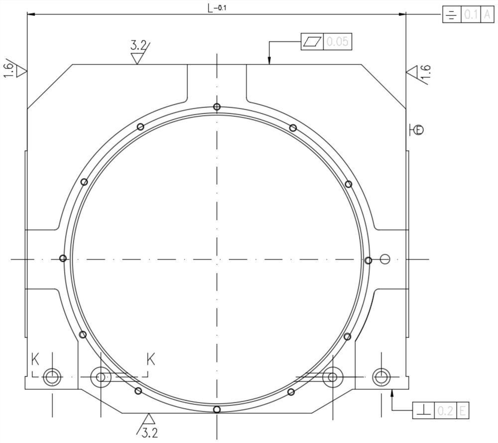
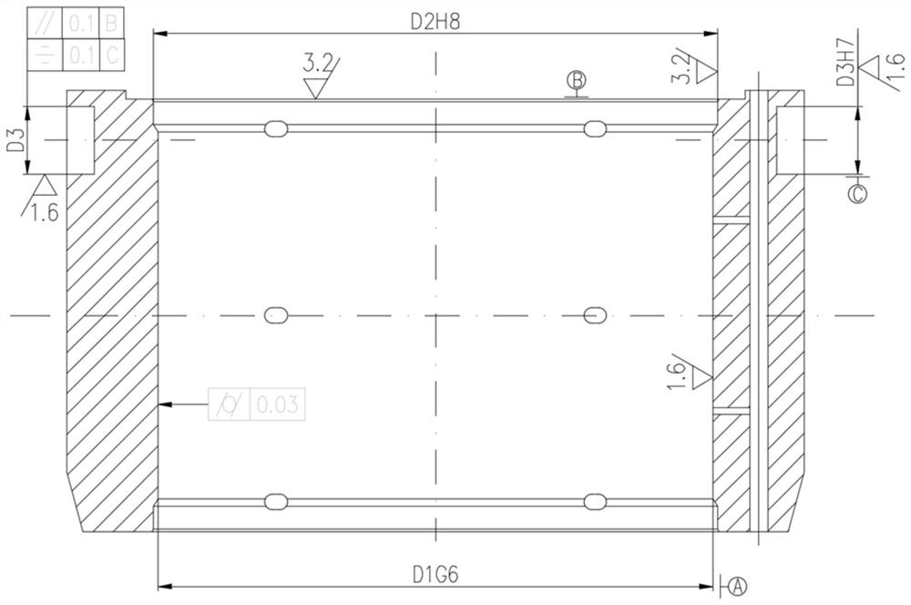
[0043] Such as Figure 1 to Figure 3 As shown, a rolling mill bearing housing is forged from high-quality alloy steel. It is installed at both ends of the symmetrically structured support roll on a large rolling mill and can be adjusted up and down with the pressure of the oil cylinder. It is embedded in and in contact with the rolling mill archway. The sliding surface of the bearing is equipped with a copper slide plate; on the bearing seat of the rolling mill, the precision of the bearing hole is G6, the surface roughness is Ra1.6, and the cylindricity is 0.03mm, the precision of the matching hole of the bearing end cover is H8, the surface roughness is Ra3.2, The surface roughness of the sliding surface is Ra1.6, the symmetry of the center of the bearing hole is 0.1mm, the flatness of the upper surface is 0.05mm, and the verticality of the lower slid...


PUM

PropertyMeasurementUnit
Cylindricityaaaaaaaaaa

Abstract

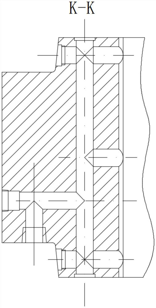
The invention discloses a rolling mill bearing base and a manufacturing method thereof. The rolling mill bearing base is forged and processed from high-quality alloy steel, and is mounted at the two ends of a supporting roller of a symmetrical structure on a large rolling mill; the sliding surface which is in contact with a rolling mill memorial gate is equipped with a copper slide plate; precision of a bearing hole is G6, surface roughness of the bearing hole is Ra1.6 and cylindricity of the bearing hole is 0.03mm; precision of a bearing end cover matching hole is H8, surface roughness of thebearing end cover matching hole is Ra3.2, surface roughness of sliding surfaces at the two sides is Ra1.6, degree of symmetry on the bearing hole is 0.1 mm, flatness of an upper surface is 0.05mm, perpendicularity, to the sliding surfaces, of a lower surface is 0.2 mm, the two sliding surfaces are symmetrically equipped with dowel pin holes, precision of the dowel pin holes is H7, surface roughness of the dowel pin holes is Ra1.6, degree of symmetry on the bearing hole is 0.1 mm, and center perpendicularity to the bearing hole is 0.1 mm. An intensive lubricating system is adopted, and a ratioof hole depth to hole diameter of an oil inlet and outlet is 20 or higher. The rolling mill bearing base can meet the requirements of quickly replacing and interchanging a supporting roller, is accurate in positioning, is good in cooling and lubricating effect, is high in precision, reduces rolling mill faults, and guarantees the processing quality.

Description

technical field [0001] The invention belongs to the field of metallurgy and steel rolling machinery, and in particular relates to a rolling mill bearing seat and a manufacturing method thereof. Background technique [0002] The rolling mill chock is one of the important parts of the rolling equipment. The rolling mill chock is the direct bearer of the roll load, and the rolling force is transmitted to the rolling mill chock through the bearing. Therefore, whether the structure of the rolling mill chock is reasonable and whether the accuracy meets the requirements It has an important impact on the service life of the bearing and the safe operation of the rolling mill. Bearing housings of rolling mills bear heavy loads, have complex structures, require high precision, have long manufacturing cycles, and are easily deformed during processing. They are the key research objects of many professional manufacturers. [0003] For the existing bearing housings of rolling mills, some ...

Claims


Application Information

Patent Timeline
Patent Type & Authority Patents(China)
IPC IPC(8): B21B31/02B23P15/00C21D9/40
Inventor 李良洪陈刚王文飙陈丽娟何明生
Owner 武汉钢铁有限公司
Learn More