
Chemical equipment tail gas treatment device

A technology for tail gas treatment and chemical equipment, which is applied in the direction of combined devices, chemical instruments and methods, and separation of dispersed particles. It can solve problems such as inconvenience, complex structure, and short residence time of flue gas, so as to prevent packing compaction and increase processing paths. , the effect of prolonging the processing time

Active Publication Date: 2019-05-10
山东欣润高分子材料有限公司
View PDF7 Cites 4 Cited by
  • Summary
  • Abstract
  • Description
  • Claims
  • Application Information

AI Technical Summary

Problems solved by technology

[0003] The purpose of the present invention is to provide a chemical equipment tail gas treatment device, which overcomes the short residence time of flue gas in the chemical equipment tail gas treatment device in the aforementioned prior art or the incomplete reaction caused by the compaction of the filler, and the need for more sprays of medicine in the flue gas dust removal process. The synergy of the shower head or the more complex water curtain mechanism leads to complex structure, dehydration of the demist mechanism, inconvenient replacement and inconvenient fixing of pulleys.

Method used


Image

  • Chemical equipment tail gas treatment device
  • Chemical equipment tail gas treatment device
  • Chemical equipment tail gas treatment device

Examples


Embodiment Construction

[0027] In order to make the purpose, technical solutions and advantages of the embodiments of the present invention more clear, the technical solutions in the embodiments of the present invention will be clearly and completely described below in conjunction with the drawings in the embodiments of the present invention.

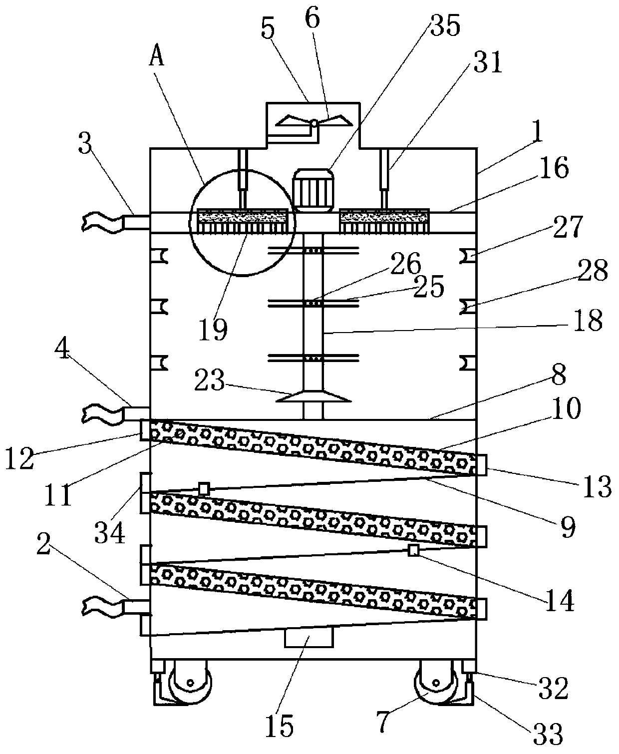
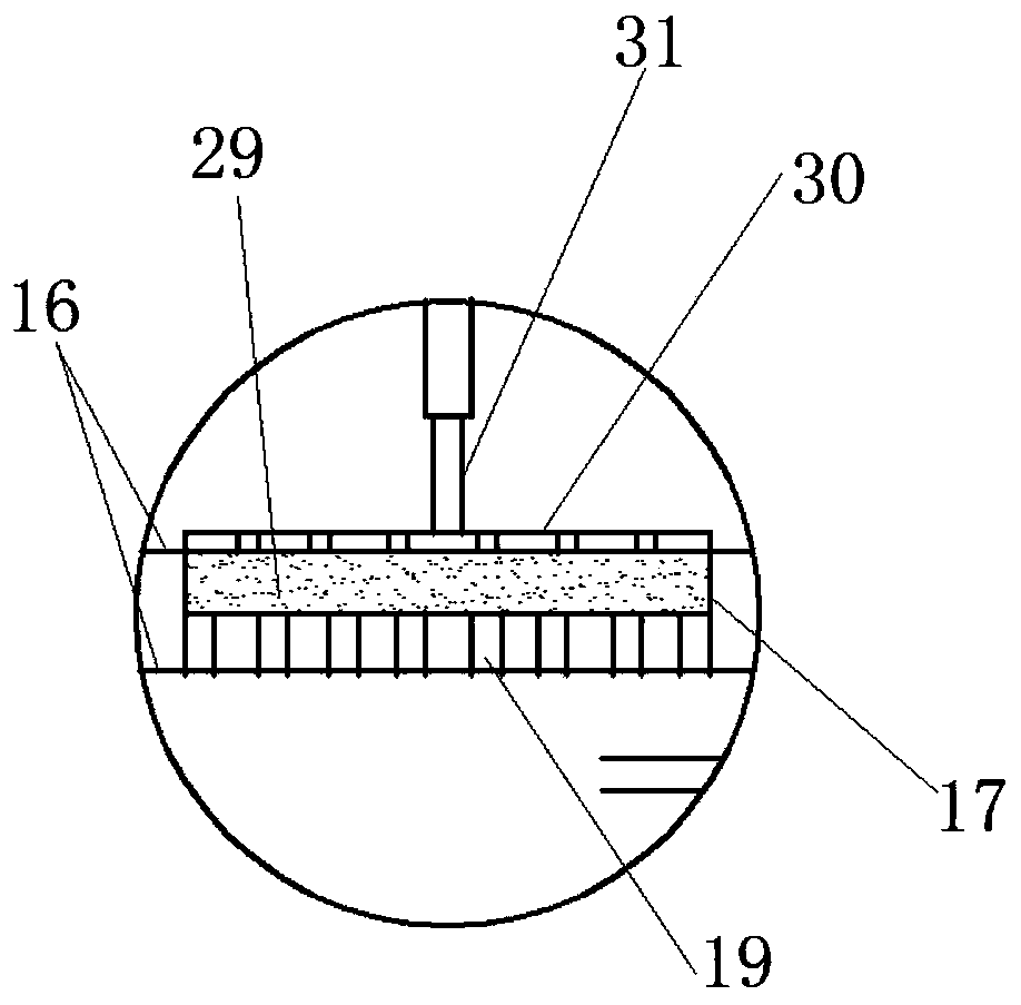
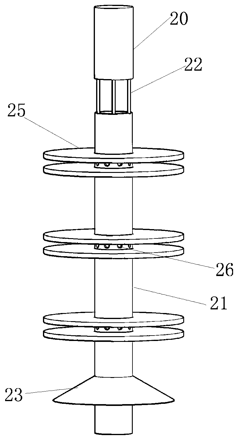
[0028] Such as Figure 1-5 In the shown embodiment, a chemical equipment tail gas treatment device includes a casing 1, a raw flue gas inlet pipe 2 arranged on the side of the casing 1, a water inlet pipe 3, a sewage pipe 4, and a clean smoke pipe arranged on the top of the casing 1. The gas exhaust outlet 5, the exhaust fan 6 arranged in the clean smoke exhaust outlet 5, and the walking wheel 7 arranged at the bottom of the housing 1, the middle end of the housing 1 is provided with a transverse partition 8, and the housing 1 A water delivery mechanism is fixed at the middle and upper end, and the horizontal partition 8 and the water delivery mechanism divide...


PUM


Abstract

The invention relates to the technical field of tail gas treatment, in particular to a chemical equipment tail gas treatment device. The chemical equipment tail gas treatment device is characterized in that a transverse partition plate is arranged in the middle of the inside of a shell, a water delivery mechanism is fixed to the middle upper end of the shell, the inside of the shell is sequentially divided into a tail gas filter chamber, a tail gas dust removal chamber and a tail gas demisting chamber from bottom to top by the transverse partition plate and the water delivery mechanism, harmful pollutants in tail gas can be removed by the tail gas filter chamber by means of multistage filtering, dust in the tail gas can be efficiently removed by the tail gas dust removal chamber by the aidof formed smoke curtains and multistage water curtains, and the tail gas can be efficiently demisted by the tail gas demisting chamber by the aid of a simple demisting mechanism. The chemical equipment tail gas treatment device has the advantages that the chemical equipment tail gas treatment device is long in flue gas retention time in procedures for carrying out adsorption reaction on harmful substances in the tail gas, and fillers are difficult to harden; flue gas dust removal procedures can be thoroughly carried out, excellent synergistic effects can be realized, the chemical equipment tail gas treatment device is simple in structure, the demisting mechanism is convenient to dehydrate and long in service time, and the locations of travel wheels are convenient to fix.

Description

technical field [0001] The invention relates to the technical field of tail gas treatment, in particular to a chemical equipment tail gas treatment device. Background technique [0002] Chemical equipment is a part of chemical machinery. Chemical machinery consists of two parts. One is chemical machinery, which mainly refers to equipment such as fans, compressors, and various pumps for fluid transportation. The main components are moving machinery, generally called chemical engineering. machine. The second is that chemical equipment mainly refers to machinery whose components are static, such as separation equipment such as towers, containers, reactor equipment, etc., sometimes also called non-standard equipment. When chemical equipment is in operation, exhaust gas will be generated, and the exhaust gas will be directly discharged into the atmosphere, which will cause serious pollution to the environment. It is necessary to filter the exhaust gas and then discharge it. Exi...

Claims


Application Information

Patent Timeline
IPC IPC(8): B01D50/00
Inventor 司佳丽
Owner 山东欣润高分子材料有限公司
Learn More