Low clearance single track tunnel contact wire positioning device

A tunnel contact and line positioning technology, which is applied in overhead lines, power lines, transportation and packaging, etc., can solve the problems of bow-shaped wrist arm deformation and inability to meet the requirements of line use, so as to increase reliability, strong field adaptability, and guarantee The effect of safe operation

Pending Publication Date: 2019-05-07
CHINA RAILWAY HIGH SPEED ELECTRIFICATION EQUIP CORP LTD
View PDF6 Cites 3 Cited by
  • Summary
  • Abstract
  • Description
  • Claims
  • Application Information

AI Technical Summary

Problems solved by technology

Although this connection method does not cause a hard point on the contact wire, the bow-shaped wrist arm is deformed during the use of the line due to the excessive torque on the bow-shaped wrist arm, so this connection method cannot meet the requirements of the line. Requirements

Method used


Image

  • Low clearance single track tunnel contact wire positioning device
  • Low clearance single track tunnel contact wire positioning device
  • Low clearance single track tunnel contact wire positioning device

Examples


Embodiment Construction

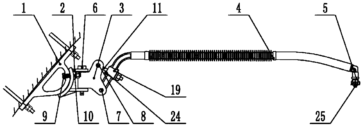
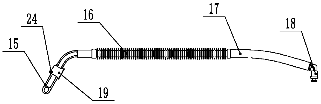
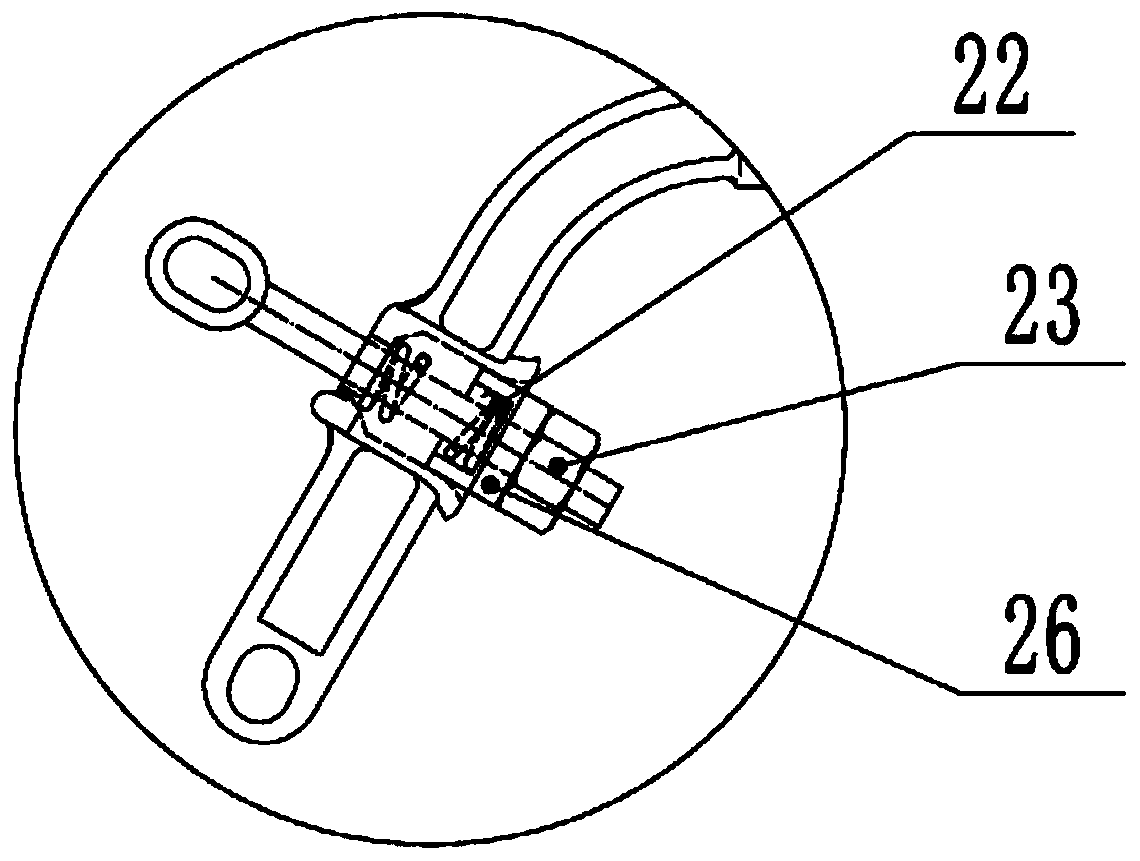
[0019] Attached below Figure 1-6 The present invention will be described in detail with specific embodiments.

[0020] A contact line positioning device for a low-headroom single-line tunnel, including an arcuate base 1, connecting ears 2, rotating ears 3, an elastic insulating limiter 4, and a positioning wire clamp 5; the arcuate base 1 is fixed in the tunnel by anchor bolts On the wall, and the front end of the bow-shaped base 1 is fixed with a connecting ear 2 through a bolt pair 9, and the front end of the connecting ear 2 is hinged with a rotating double ear 3 through a pin 6; the rear end of the elastic insulating limit locator 4 is a bending section , and the end of the bending section is hinged between the lower ears of the front end of the rotating double ear 3 through the bolt pin I7, the middle part of the bending section is equipped with an elastic pull rod 11, and the upper end of the elastic pull rod 11 is hinged at the front end of the rotating double ear 3 th...


PUM


Abstract

A low clearance single track tunnel contact wire positioning device comprises an arched base, a connecting double lug, a rotating double lug, an elastic insulated limiting positioner and a positioningwire clip; the arched base is fixed on the wall of a tunnel through a bolt; the connecting double lug is fixed at the front end of the arched base through a bolt pair; the rotating double lug is hinged to the front end of the connecting double lug through a pin shaft; the rear end of the elastic insulated limiting positioner is a bent section; the end part of the bent section is hinged between lower lugs at the front end of the rotating double lug through a bolt pin I; an elastic pull rod is mounted at the middle part of the bent section; the upper end of the elastic pull rod is hinged between upper lugs at the front end of the rotating double lug through a bolt pin II; and the positioning wire clip is fixed under the front end of the elastic insulated limiting positioner. According to the low clearance single track tunnel contact wire positioning device, shortcomings in the prior art are eliminated, the elastic uniformity of an overhead line system is improved, the current collectingquality of a pantograph type current collector is improved, and therefore, the safety running of a locomotive is guaranteed.

Description

technical field [0001] The invention belongs to the technical field of catenary systems for electrified railways, and in particular relates to a positioning device for contact lines of low clearance single-track tunnels. Background technique [0002] At present, the suspension of the contact line in the electrified low-clearance single-track tunnel mostly uses horizontal suspension and a bow-shaped single-support wrist-arm structure, and the line running speed is below 120km / h. With the development of my country's electrified railway, the running speed of the train puts forward higher requirements for the catenary system in the low headroom single-track tunnel. The contact line in the horizontal suspension device is connected and fixed by the insulating locator. During the actual operation of the line, it is found that the insulating locator concentrates all its own weight (about 9.5kg) on ​​the contact line at the contact line positioning point, forming a negative impact on...

Claims


Application Information

Patent Timeline
Patent Type & Authority Applications(China)
IPC IPC(8): B60M1/20B60M1/234B60M1/24
Inventor 索会敏龚建刚林建邓相龙杨佳王彦哲冯勇李立楚晓龙
Owner CHINA RAILWAY HIGH SPEED ELECTRIFICATION EQUIP CORP LTD
Why Eureka
Try Eureka