


Quick Research
Generate reliable direction feasibility study reports for your R&D in just a few steps.

Technical Q&A
Discover and master advanced knowledge NOW. Basics, ideas, possibilities, all at once.

Find Solutions
As an expert in R&D theories, this can generate solutions to your technical problems instantly.

Evaluate Feasibility
Analyze your overall solution with one click, know your potential R&D risks in advance.

Monitor Landscape
Get weekly tech updates, stay abreast of the latest tech innovations and key insights.
Equipment temperature regulator
A temperature regulating device and equipment technology, applied in lighting and heating equipment, heating/cooling equipment, transportation and packaging, etc., can solve the difficulty of piping arrangement, increase the number of multiple thermosiphon circuit components and design man-hours, and complicated piping arrangement and other problems, to achieve the effect of good space utilization efficiency and improved vehicle loadability
- Summary
- Abstract
- Description
- Claims
- Application Information
AI Technical Summary
Problems solved by technology
Method used
Image

Examples
no. 1 approach
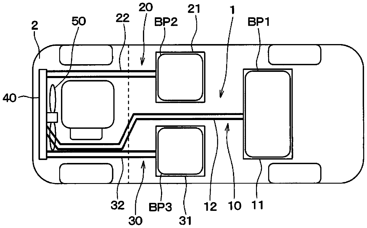
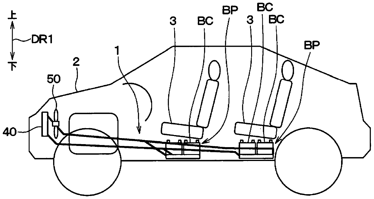
[0071] The facility temperature control device of the present embodiment is mounted on electric vehicles (hereinafter, simply referred to as "vehicles") such as electric vehicles and hybrid vehicles. Such as Figure 1 ~ Figure 4 As shown, the device temperature adjustment device 1 functions as a cooling device that cools a secondary battery BP (hereinafter referred to as “battery BP”) mounted on a vehicle 2 . In addition, in the drawing, symbols BP1 , BP2 , and BP3 are assigned to batteries BP arranged in various parts of the vehicle 2 .
[0072] First, the battery BP which is the target device cooled by the device temperature adjustment device 1 will be described.
[0073] In the vehicle 2 equipped with the equipment temperature control device 1 , electric power stored in a power storage device (in other words, a battery pack) including the battery BP as a main component is supplied to the vehicle running motor via an inverter or the like. When the vehicle is running and th...
no. 2 approach
[0105] A second embodiment will be described. In the second embodiment, the configuration of the main condenser 40 is changed from that of the first embodiment, and since other parts are the same as those of the first embodiment, only the parts different from the first embodiment will be described.
[0106] Such as Figure 6 and Figure 7 As shown, the main condenser 40 of the second embodiment is equipped with the first to third heat exchange units 120 , 220 , and 320 respectively provided in the first to third thermosyphon circuits 10 , 20 , and 30 and the refrigeration cycle 60 . The evaporator 61 is formed integrally. The main condenser 40 is configured to exchange heat between the working fluid flowing through the first to third heat exchange units 120 , 220 , and 320 and the refrigerant circulating through the refrigeration cycle 60 . That is, in the second embodiment, the predetermined cooling and heating supply medium that exchanges heat with the working fluid flowi...
no. 3 approach
[0115] A third embodiment will be described. The third embodiment also changes the structure of the main condenser 40 with respect to the first and second embodiments, and since other parts are the same as those of the first and second embodiments, only the parts different from those of the first and second embodiments Be explained.
[0116] Such as Figure 8 As shown, the main condenser 40 of the third embodiment is composed of the first to third heat exchange parts 120, 220, 320 respectively provided in the first to third thermosiphon circuits 10, 20, 30 and the cooling water circuit 80. A part of the water channel 86 is integrally formed. The main condenser 40 is configured to exchange heat between the working fluid flowing through the first to third heat exchange units 120 , 220 , and 320 and the cooling water flowing through the water passage 86 of the cooling water circuit 80 . That is, in the third embodiment, the predetermined cooling fluid that exchanges heat with ...
PUM
 Abstract
Description
Claims
Application Information
 - R&D Engineer
- R&D Manager
- IP Professional
- Industry Leading Data Capabilities
- Powerful AI technology
- Patent DNA Extraction
Browse by: Latest US Patents, China's latest patents, Technical Efficacy Thesaurus, Application Domain, Technology Topic, Popular Technical Reports.
© 2024 PatSnap. All rights reserved.Legal|Privacy policy|Modern Slavery Act Transparency Statement|Sitemap|About US| Contact US: help@patsnap.com