Bridge detection device
A technology for bridge inspection and bottom plate, applied in the direction of measuring devices, instruments, etc., can solve the problems of lack of anti-overturning function, shaking of the inspection device, low inspection efficiency, etc., and achieve the effect of simple structure, easy operation and strong practicability.
- Summary
- Abstract
- Description
- Claims
- Application Information
AI Technical Summary
Problems solved by technology
Method used
Image

Examples
Embodiment 1
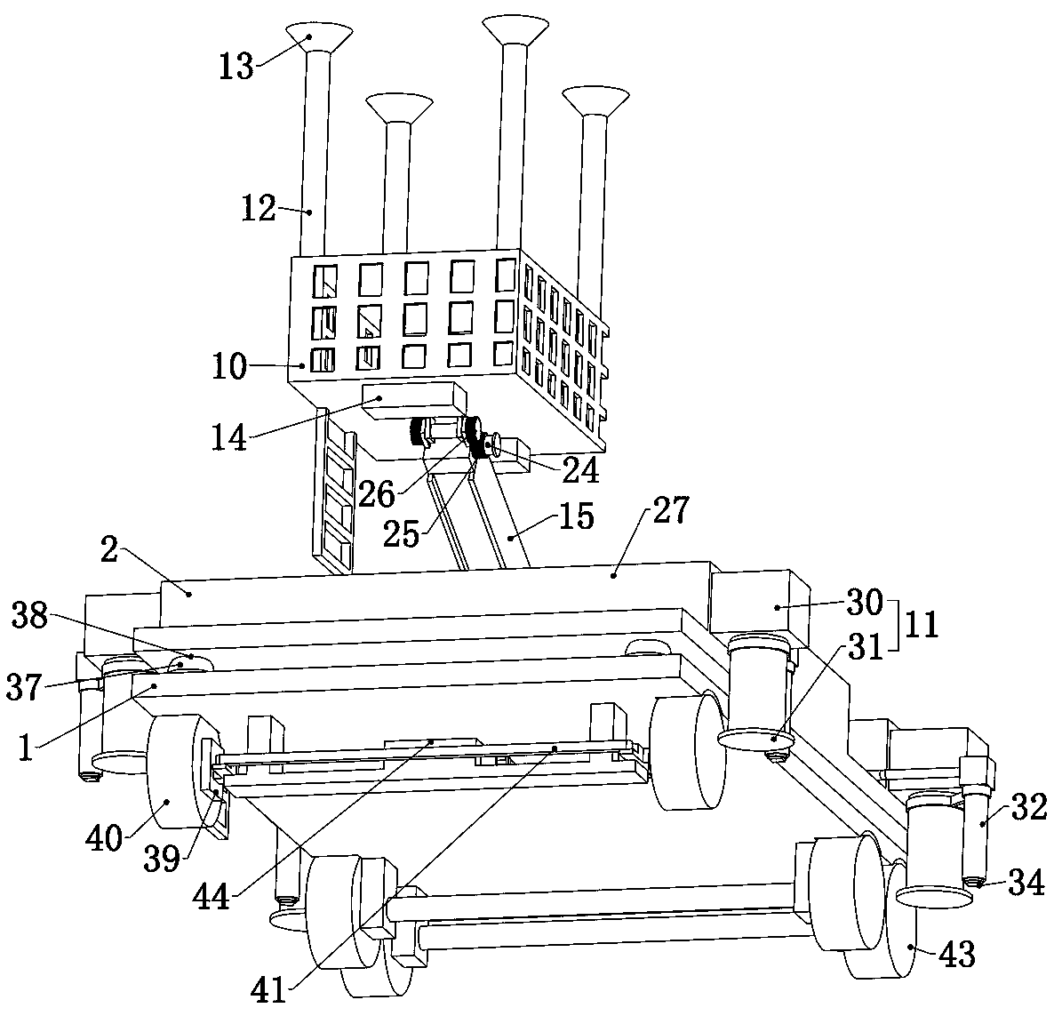
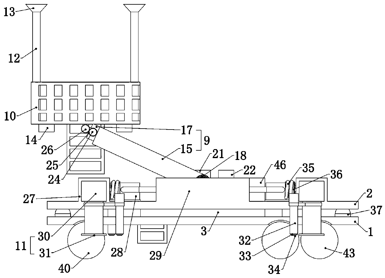
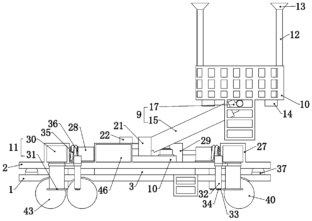
[0039]Embodiment 1, the present invention is a bridge detection device, including a base plate 1, the base plate 1 is the basis of the device, and tires are connected to it in rotation on both sides, and the base plate 1 provides a fixed foundation for the subsequent structure through the contact between the tires and the ground. To facilitate the movement of the device, the side of the base plate 1 is fixedly connected with a ladder, so that the inspectors can board the device. It is characterized in that the load-bearing plate 2 is connected to the base plate 1, and the specific contact connection method can be A number of load-bearing columns are fixedly connected to the bottom plate 1, and the load-bearing plate 2 is placed on the load-bearing columns, or other common contact connection methods can be used. The direction-changing ring gear is fixedly connected to the bottom plate 1, and the The direction-changing ring gear is meshed with a direction-changing planetary wheel...
Embodiment 2
[0040] Embodiment 2. On the basis of Embodiment 1, this embodiment provides a specific structure in which the platform 10 is adsorbed on the lower surface of the bridge, so as to ensure that the platform 10 can be adsorbed on the lower surface of the bridge after reaching the specified position. Specifically, the The four corners of the platform 10 are fixedly connected with hollow columns 12, the upper ends of the four hollow columns 12 are connected with vacuum suction cups 13, and the four hollow columns 12 are fixedly connected to the lower end surface of the platform 10 through air pipes. The vacuum pump 14 is connected, and the height of the hollow column 12 should be higher than the average height of the human body, but at the same time its height should not be too high, because the height of the hollow column 12 is the distance between the platform 10 and the lower surface of the bridge, too far is not conducive to detection For the detection of personnel, the height of...
Embodiment 3
[0041] Embodiment 3, on the basis of Embodiment 1, this embodiment provides a specific structure of the hydraulic telescopic arm 9 to ensure that the hydraulic telescopic arm 9 can lift the platform 10 to the required position Specifically, the hydraulic telescopic arm 9 includes a bottom arm 15 rotatably connected to the turntable 8, a middle arm 16 is slidably connected to the bottom arm 15, and an upper arm is slidably connected to the middle arm 16. 17. The upper end of the upper arm 17 is rotatably connected to the platform 10. The bottom arm 15 and the middle arm 16 are hollow cylindrical structures with one end open. The middle arm 16 and the bottom arm 15 The inner surface is closely attached, the upper arm 17 is a solid cylindrical structure, the upper end of the upper arm 17 is rotatably connected to the platform 10, and when the hydraulic telescopic arm 9 needs to be extended, the bottom arm 15 Fill the interior with hydraulic oil. After the hydraulic oil fills the ...
PUM
 Abstract
Description
Claims
Application Information
 - R&D
- Intellectual Property
- Life Sciences
- Materials
- Tech Scout
- Unparalleled Data Quality
- Higher Quality Content
- 60% Fewer Hallucinations
Browse by: Latest US Patents, China's latest patents, Technical Efficacy Thesaurus, Application Domain, Technology Topic, Popular Technical Reports.
© 2025 PatSnap. All rights reserved.Legal|Privacy policy|Modern Slavery Act Transparency Statement|Sitemap|About US| Contact US: help@patsnap.com