Al technical title is built by PatSnap Al team. It summarizes the technical point description of the patent document.
A production equipment and controller technology, applied in chemical instruments and methods, dissolving, mixing machines, etc., can solve problems such as cross-contamination of mixing different products, failure of equipment to discharge, and blockage of the discharge port, so as to improve production efficiency and reduce production costs. The effect of producing the body and improving the quality of the finished product
Inactive Publication Date: 2019-04-30
天长市龙亨电子有限公司
View PDF6 Cites 7 Cited by
Summary
Abstract
Description
Claims
Application Information
AI Technical Summary
This helps you quickly interpret patents by identifying the three key elements:
Problems solved by technology
Method used
Benefits of technology
Problems solved by technology
[0004] The purpose of the invention is to provide a controller housing production equipment to solve the problem that in the stirring process of the traditional mixing equipment proposed in the above background technology, the position of the mixing drum is fixed, and the raw materials can only be mixed in one direction, the mixing effect is poor, and the mixing drum A large amount of raw material residues will adhere to the inner wall. On the one hand, it will cause waste of raw materials. On the other hand, there will be cross-contamination when mixing different products. During the discharging process, the raw materials may block the discharge port, resulting in the failure of the equipment to discharge The problem
Method used
Image
Click on the blue label to locate the original text in one second.
Reading with bidirectional positioning of images and text.
Examples
Embodiment Construction
[0019] The technical solutions in the embodiments of the invention will be clearly and completely described below in conjunction with the accompanying drawings in the embodiments of the invention. Obviously, the described embodiments are only a part of the embodiments of the invention, rather than all the embodiments. Based on the embodiments in the invention, all other embodiments obtained by those of ordinary skill in the art without creative work shall fall within the scope of protection of the invention.
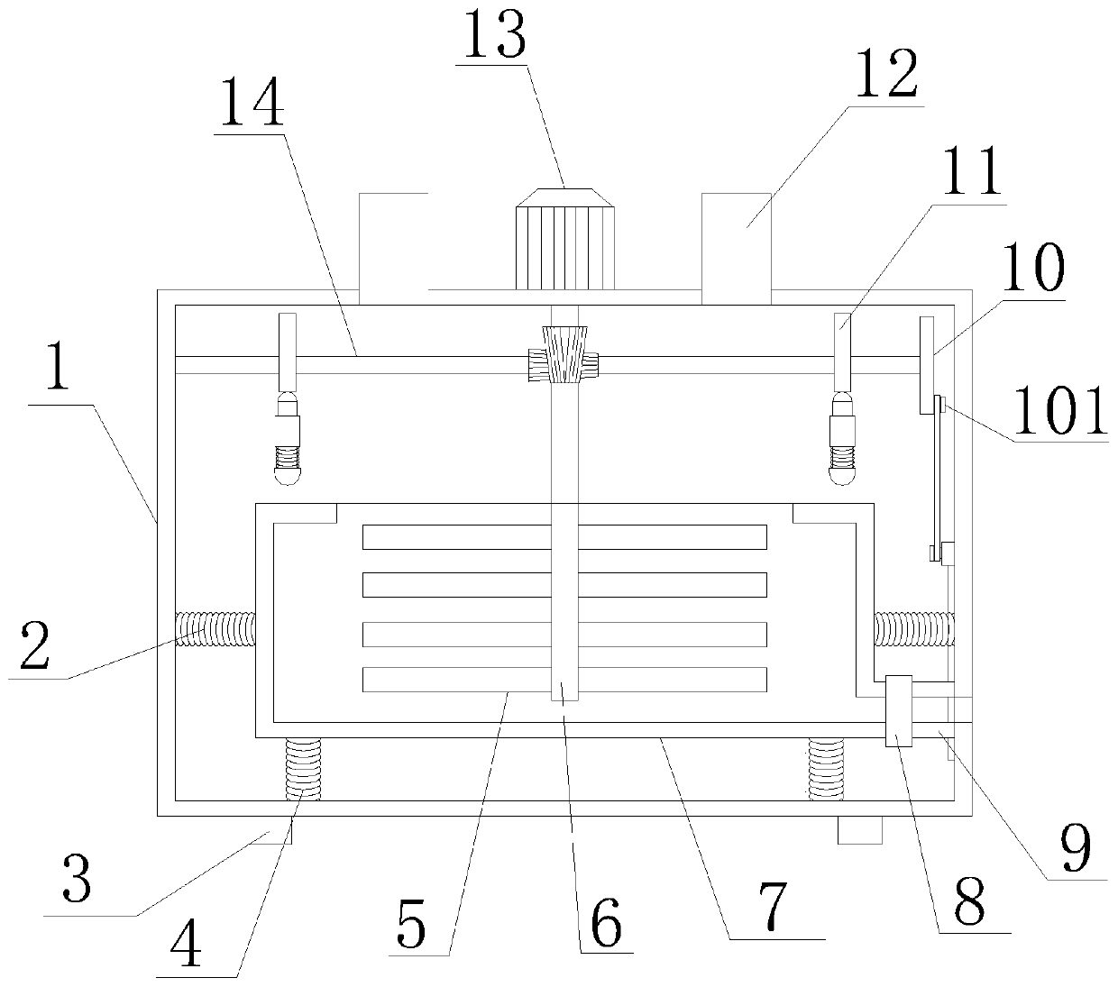
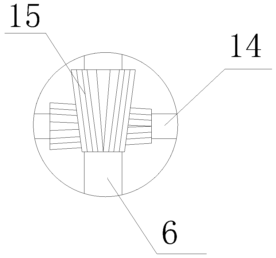
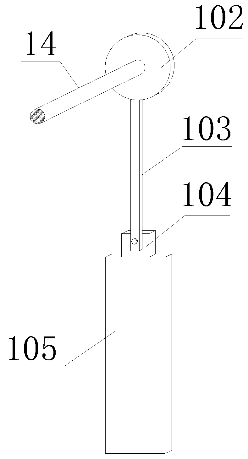
[0020] See Figure 1-3 , The invention provides a technical solution: a controller housing production equipment, including a device main body, an intermittent discharging mechanism 10 and an auxiliary stirring mechanism 11, the device main body including an outer box body 1, a leg 3, a connecting spring 4, and a stirring blade 5. Mixing shaft 6, inner box 7, discharge valve 8, discharge port 9, loading port 12, drive motor 13, drive shaft 14 and helical gear assembly 15, th...
PUM
Abstract
The invention relates to a controller shell production device. The device comprises connecting springs, stirring blades, a stirring shaft, a transmission shaft, cams, transmission rods, vibrating hammers, telescopic springs, guide sleeves, ball bodies, a pin shaft, a rotating disc, a connecting rod, a sliding block and a material blocking plate, the stirring shaft is rotatably connected to the inside of an outer box body, the stirring blades are arranged on the stirring shaft, a discharging valve is arranged at a discharging port, the cam is arranged on the transmission shaft, a section of every transmission rod is located in the corresponding guiding sleeve, the vibration hammers are arranged at the bottom ends of the transmission rods, the ball bodies are arranged at the top ends of thetransmission rods, the vibrating hammers are connected to the bottom ends of the guiding sleeves through the telescopic springs, the rotating disc is arranged on the transmission shaft, the pin shaftis fixed on the right end surface of the rotating disc, the material blocking plate is fixedly connected with the sliding block, and two ends of the connecting rod are respectively connected to the pin shaft and the front end surface of the sliding block. The device has the advantages of good structure, reasonable design, simplicity operation, reduction of the production body, improvement of the product quality, ensuring of the production efficiency, improvement of the production effect, wide application prospect and strong creativity.
Description
Technical field [0001] The invention relates to the field of controller production equipment, in particular to a controller housing production equipment. Background technique [0002] Electric vehicles, namely electric vehicles, also known as electric vehicles. Electric vehicles are divided into AC electric vehicles and DC electric vehicles. Generally speaking, an electric vehicle is a vehicle in which a battery is used as an energy source, and electrical energy is converted into mechanical energy through components such as a controller and a motor to control the current and change the speed. The first electric car was manufactured in 1881. The inventor was French engineer Gustave Trouvé. This is a tricycle powered by lead-acid batteries. It is driven by a DC motor. Today, Electric vehicles have undergone tremendous changes, and their types are also diverse. In November 2018, the Ministry of Industry and Information Technology, the National Development and Reform Commission an...
Claims
Application Information
Patent Timeline
Application Date:The date an application was filed.
Publication Date:The date a patent or application was officially published.
First Publication Date:The earliest publication date of a patent with the same application number.
Issue Date:Publication date of the patent grant document.
PCT Entry Date:The Entry date of PCT National Phase.
Estimated Expiry Date:The statutory expiry date of a patent right according to the Patent Law, and it is the longest term of protection that the patent right can achieve without the termination of the patent right due to other reasons(Term extension factor has been taken into account ).
Invalid Date:Actual expiry date is based on effective date or publication date of legal transaction data of invalid patent.