
Foundation reinforcement device and method

A technology for foundation reinforcement and foundation area, which is used in infrastructure engineering, soil protection, construction, etc., can solve the problems of low grouting efficiency and difficulty in fully injecting the slurry into the soil, and achieve the effect of improving efficiency.

Inactive Publication Date: 2019-04-23
CHINA THREE GORGES UNIV
View PDF7 Cites 11 Cited by
  • Summary
  • Abstract
  • Description
  • Claims
  • Application Information

AI Technical Summary

Problems solved by technology

[0003] The technical problem to be solved by the present invention is to provide a foundation reinforcement device and method, which can solve the problem that the grout is difficult to fully inject into the soil and the grouting efficiency is low. The combination of deep hole grouting and local vacuum suction drainage makes the grout rapidly Penetrating into the soil to reinforce the soil, saving time and effort

Method used


Image

  • Foundation reinforcement device and method
  • Foundation reinforcement device and method
  • Foundation reinforcement device and method

Examples


Embodiment 1

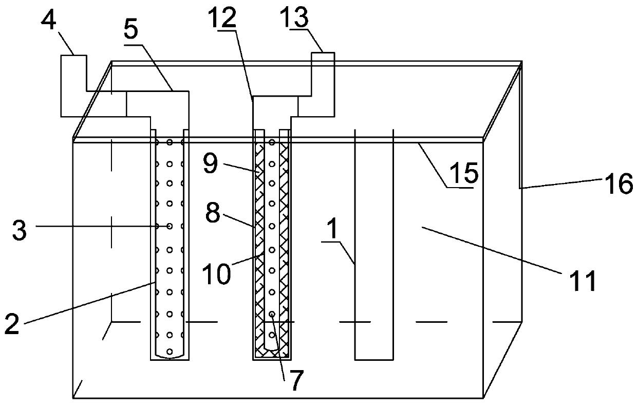
[0036] Such as Figure 1-Figure 3 As shown, a foundation reinforcement device includes spacers 16 with open upper and lower end surfaces inserted into the soil around the foundation area 11 to be reinforced. The foundation area 11 to be reinforced is evenly arranged with N columns of boreholes 1, and each column drills The number of holes 1 is M, N≥2, M≥1, the grouting device and the suction device are respectively matched with the drilling 1; the top surface of the foundation area 11 to be reinforced is laid with an isolation film 15, and the foundation area to be reinforced 11 The edge position is closed and connected with the isolation film 15;

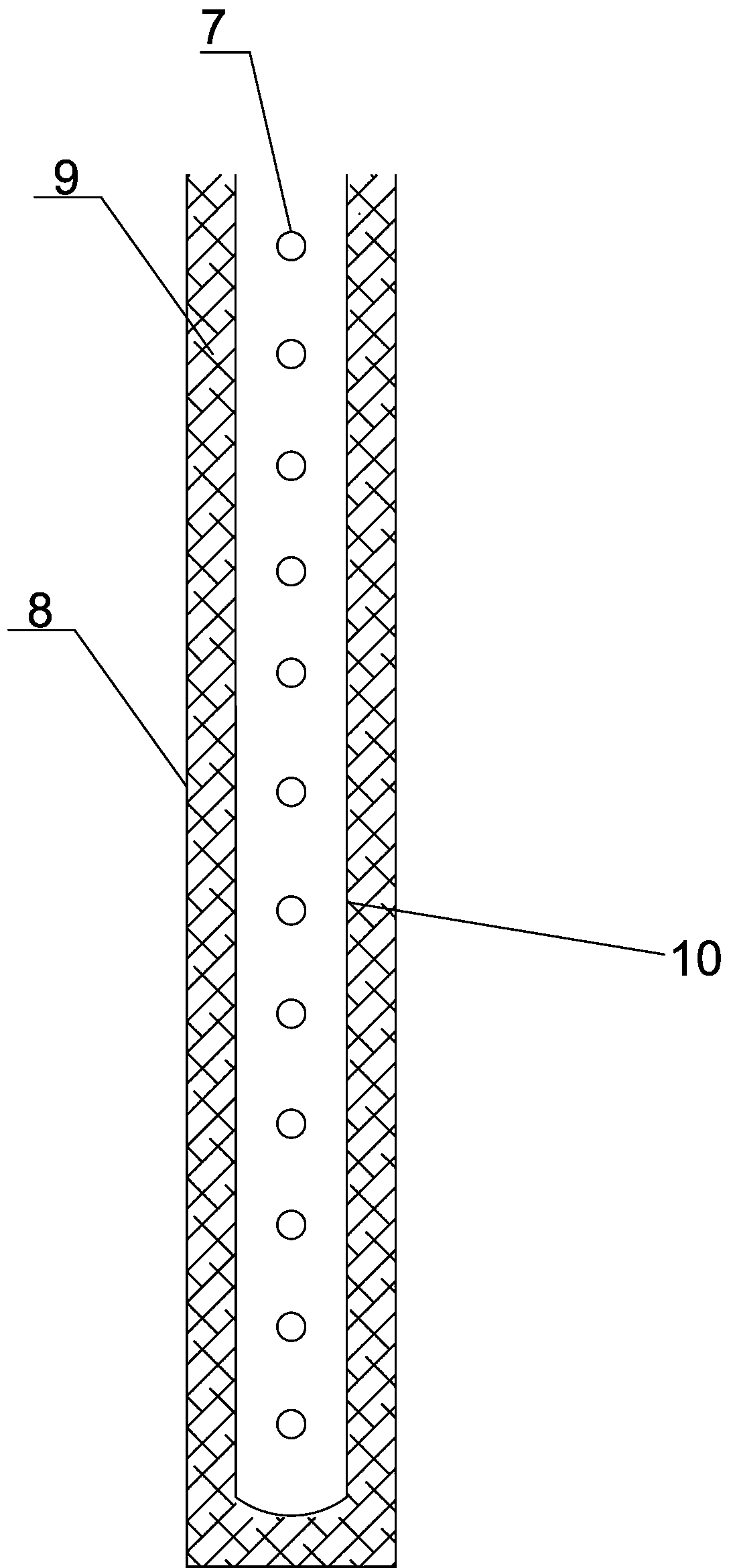
[0037] The suction device includes a suction pipe body, the suction pipe body includes a suction pipe 10 with an open top, the pipe wall of the suction pipe 10 is evenly arranged with a plurality of suction holes 7, and the suction pipe 10 is covered with a metal mesh. Layer 8, the space between the suction pipe 10 and the metal m...

Embodiment 2

[0043] Such as Figure 4 Shown, a kind of method that adopts above-mentioned device to carry out foundation reinforcement, this method comprises the following steps:

[0044] Step 1: Determine the foundation area 11 to be reinforced, and insert the isolation body 16 into the soil outside the foundation area 11 to be reinforced;

[0045] Step 2: Drill N columns of boreholes 1 in the foundation area 11 to be reinforced, the number of each column of boreholes 1 is M, N=2, M≥1; the distance between every two boreholes 1 is much greater than The diameter of the borehole 1 (preferably 2-5 times the diameter);

[0046] Step 3: Lay an isolation film 15 on the top surface of the foundation area 11 to be reinforced, and seal and connect the edge of the foundation area 11 to be reinforced with the isolation film 15;

[0047] Step 4: Drill holes at the appropriate positions of the isolation membrane 15 in the foundation area 11 to be reinforced, insert the grouting pipe 2 into each dril...

Embodiment 3

[0051] Such as Figure 5 Shown, a kind of method that adopts above-mentioned device to carry out foundation reinforcement, this method comprises the following steps:

[0052] Step 1: Determine the foundation area 11 to be reinforced, and insert the isolation body 16 into the soil outside the foundation area 11 to be reinforced;

[0053] Step 2: Drill N columns of boreholes 1 in the foundation area 11 to be reinforced, the number of each column of boreholes 1 is M, N>2, M≥1; the distance between every two boreholes 1 is much greater than The diameter of the borehole 1 (preferably 2-5 times the diameter);

[0054] Step 3: Lay an isolation film 15 on the top surface of the foundation area 11 to be reinforced, and seal and connect the edge of the foundation area 11 to be reinforced with the isolation film 15;

[0055] Step 4: Drill holes at appropriate positions in the foundation area 11 to be reinforced, insert the grouting pipe 2 into each drill hole 1 of the first row of dril...


PUM


Abstract

A foundation reinforcement device comprises an isolator inserted inside a soil body on the periphery of a foundation area needing reinforcement, wherein the upper end face and the lower end face of the isolator are open. N columns of drill holes are evenly formed in the foundation area needing reinforcement. A grouting device and a suction device are matched with the drill holes. An isolation filmis laid on the top face of the foundation area needing reinforcement, and the edge position of the foundation area needing reinforcement is in closed connection with the isolation film. The suction device comprises a suction pipe body, wherein the suction pipe body comprises a suction pipe with the top end being open; a plurality of suction holes are evenly formed in the pipe wall of the suctionpipe. The suction pipe is sleeved with a metal screen outer layer, and the space between the suction pipe and the metal screen outer layer is filled with an isolation layer. According to the foundation reinforcement device and a foundation reinforcement method, the problems that grout is not liable to sufficiently inject into the soil body and the grouting efficiency is low can be solved; and by combining deep hole grouting and local vacuum suction drainage, the grout quickly permeates into the soil body for reinforcing the soil body, and both time and labor are saved.

Description

technical field [0001] The invention relates to the technical field of reinforcement for porous media such as soil and rock, in particular to a foundation reinforcement device and method. Background technique [0002] At present, foundation grouting mainly uses pneumatic, hydraulic or electrochemical principles to uniformly inject some curable grout into cracks or pores of various media through grouting pumps and grouting pipes, in order to fill, infiltrate and compact. Drive away the moisture and gas in the cracks and pores, and fill their positions. After hardening, the rock pattern will be cemented into a whole to form a new rock and soil mass with high strength, low compressibility, high impermeability and good stability. , thereby improving the physical and chemical properties of the foundation. However, these methods are usually time-consuming and labor-intensive, and it is difficult to fully inject the slurry to completely fill the cracks or pores of various media. ...

Claims


Application Information

Patent Timeline
Patent Type & Authority Applications(China)
IPC IPC(8): E02D3/12E02D15/02
CPCE02D3/12E02D15/02E02D2250/003
Inventor 刘杰高素芳谢晓康黎照孙涛兰俊付寅韬朱炎昊周克虎卢获郑斯源周雨舟林轩
Owner CHINA THREE GORGES UNIV
Learn More