Self-cooled emergency battery pack composed of phase change energy storage individuals
A phase-change energy storage, battery pack technology, applied in secondary batteries, circuits, electrical components, etc., can solve the problem of inability to meet the main power failure operation, high-intensity heat dissipation and safety protection requirements, and inability to meet emergency power supply battery pack installation conditions, inability to meet relevant requirements, etc., to achieve uniform and direct heat dissipation, flexible size and shape design, and no risk of electromagnetic interference
- Summary
- Abstract
- Description
- Claims
- Application Information
AI Technical Summary
Problems solved by technology
Method used
Image

Examples
specific Embodiment approach 1
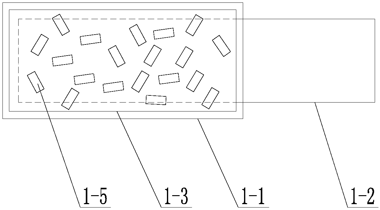
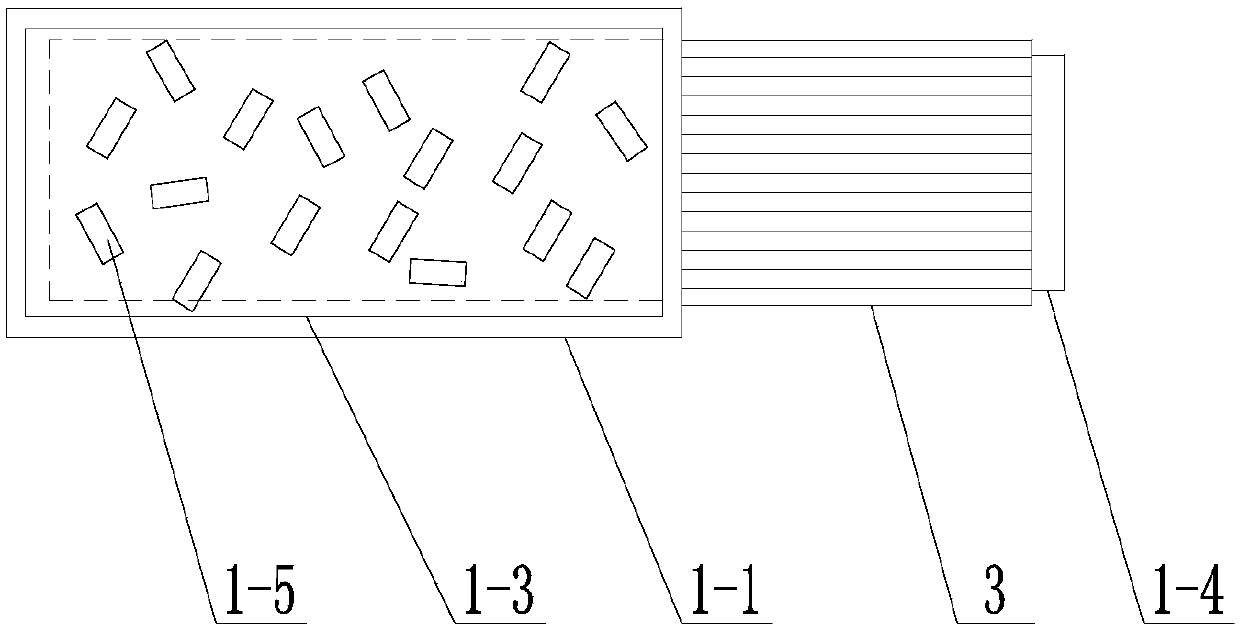
[0035] Specific implementation mode one: according to figure 1 , figure 2 , image 3 , Figure 4 , Figure 5 , Image 6 and Figure 7 Describe this embodiment. This embodiment includes an outer capsule 1-1 and a heat conduction plate 1-2. A phase change heat conductor 1-3 is arranged inside the outer capsule 1-1, and one end of the heat conduction plate 1-2 passes through the outer capsule. The body 1-1 is inserted into the phase change heat conductor 1-3, and the other end of the heat conduction plate 1-2 is arranged outside the outer capsule 1-1.
[0036] Further, the end of the heat conducting plate 1-2 outside the outer capsule 1-1 is fitted with a convective radiator 3 . The convection radiator 3 adopts finned convection radiators, which are aluminum alloy profiles, and its advantages are: high coefficient of heat dissipation, low cost, and good availability. The space between the convection radiator 3 and the heat conduction plate 1-2 is filled and fixed with hea...
specific Embodiment approach 2
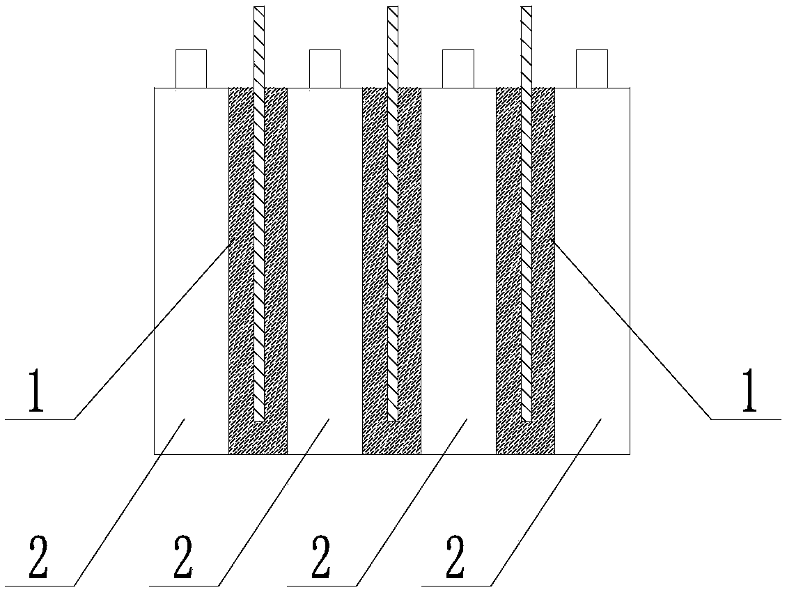
[0045] Specific implementation mode two: according to figure 1 , figure 2 , image 3 , Figure 4 , Figure 5 , Image 6 and Figure 7 Describe this embodiment. This embodiment includes a battery pack body and a plurality of phase-change energy storage cells 1. The battery pack body includes a plurality of battery cells 2. The plurality of battery cells 2 are vertically arranged side by side. Every two A gap is formed between the outer walls of adjacent battery cells 2, and a phase-change energy storage cell 1 is arranged in each gap, and each phase-change energy storage cell 1 includes an outer capsule 1-1 and a heat conduction sheet 1 -2, the outer capsule 1-1 is provided with a phase change heat conductor 1-3, and one end of the heat conduction sheet 1-2 is arranged inside the phase change heat conductor 1-3 through the outer capsule 1-1, and the heat conduction sheet 1 The other end of -2 is set outside the outer capsule 1-1. The arrangement of the outer capsule 1-1...
specific Embodiment approach 3
[0056] Specific Embodiment 3: This embodiment is a further limitation of Specific Embodiment 1 or 2. The technology and working conditions of the battery are different, and the optimal charging and discharging temperature ranges are usually different. The mass and component ratio of the phase change material of the energy storage and heat dissipation unit, the ratio of the supporting material, the heat pipe and the convection radiator need to be designed according to the type and capacity of the battery served by the thermal management system and the design working conditions of the equipment.
[0057] Let the maximum allowable temperature of the battery pack body be T h , with an initial temperature of T 0 , the heat balance formula is as follows:
[0058] Qc=∑m pi ·C pi △T+m c ·C pc ·△T+m c ·Jc+q d
[0059] In the above formula, Qc is the heat generated by the discharge of the battery pack body, and the unit is J;
[0060] m p is the mass of the outer box, supporti...
PUM
| Property | Measurement | Unit |
|---|---|---|
| thermal conductivity | aaaaa | aaaaa |
| particle diameter | aaaaa | aaaaa |
| size | aaaaa | aaaaa |
Abstract
Description
Claims
Application Information
 - Generate Ideas
- Intellectual Property
- Life Sciences
- Materials
- Tech Scout
- Unparalleled Data Quality
- Higher Quality Content
- 60% Fewer Hallucinations
Browse by: Latest US Patents, China's latest patents, Technical Efficacy Thesaurus, Application Domain, Technology Topic, Popular Technical Reports.
© 2025 PatSnap. All rights reserved.Legal|Privacy policy|Modern Slavery Act Transparency Statement|Sitemap|About US| Contact US: help@patsnap.com