
Coupling release device

A release device and axial position technology, applied in the direction of the ejection/off-machine device, etc., can solve the problems of poor fatigue resistance and the inability to select the release timing according to the control requirements, so as to achieve no high-pressure gas leakage, low use cost, and realize Effects of remote manipulation and control

Active Publication Date: 2019-04-19
SHENYANG AIRCRAFT DESIGN INST AVIATION IND CORP OF CHINA
View PDF5 Cites 3 Cited by
  • Summary
  • Abstract
  • Description
  • Claims
  • Application Information

AI Technical Summary

Problems solved by technology

In this form, the structure is simple and the cost of parts is low, but it is not suitable for use under the conditions of small separation load and multi-point simultaneous release actions. It is necessary to accurately determine the direction of separation and release, the trajectory of motion, and the driving force and acceleration during separation. Control, and the fatigue resistance is not good, and the release timing cannot be selected according to the control needs

Method used


Image

  • Coupling release device
  • Coupling release device
  • Coupling release device

Examples


Embodiment Construction

[0043] In order to make the purpose, technical solution and advantages of the application more clear, the technical solution in the embodiment of the application will be described in more detail below in conjunction with the drawings in the embodiment of the application. In the drawings, the same or similar reference numerals denote the same or similar elements or elements having the same or similar functions throughout. The described embodiments are some, but not all, embodiments of the application. The embodiments described below by referring to the figures are exemplary, and are intended to explain the present application, and should not be construed as limiting the present application. Based on the embodiments in this application, all other embodiments obtained by persons of ordinary skill in the art without creative efforts fall within the protection scope of this application. Embodiments of the present application will be described in detail below in conjunction with th...


PUM


Abstract

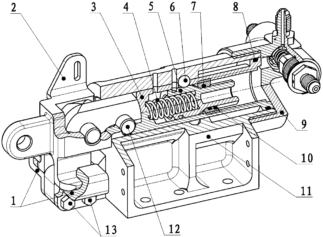
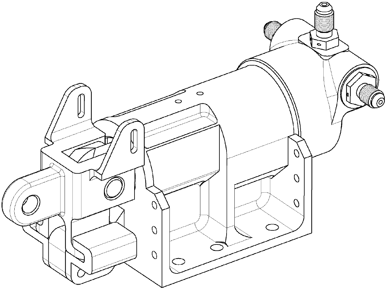
The invention provides a coupling release device, and belongs to the technical field of mechanical coupling. The coupling release device comprises a shell structure, a driving piston, a connecting guide component and two release rocker arms. The controlled driving piston penetrates a shell, one end of the connecting guide component is used for being connected with to-be-locked devices, and a groove is formed in the other end of the connecting guide component; the two release rocker arms are parallelly arranged, two ends of the two release rocker arms are arranged in the groove of the connecting guide component in a hinged manner via the same rotary shaft, a through hole which is matched with a hinge pin at an end of a first column of the driving piston can be jointly formed by the other ends of the two release rocker arms when the two release rocker arms rotate around the rotary shaft until the two release rocker arms are in mutually overlapped states, the other ends of the two releaserocker arms can extend into through holes of the shell structure along with the first column when the release rocker arms are in the mutually overlapped states, and the two release rocker arms can berestrained by the hole walls of the through holes from rotating around the rotary shaft. The coupling release device has the advantage that the coupling release device can have quick release and separation functions and can be remounted, locked and coupled at original mounting locations.

Description

technical field [0001] The present application belongs to the technical field of mechanical coupling, and in particular relates to a coupling release device. Background technique [0002] The coupling release device is used to fix the locking piece and release the locking piece when necessary. It is often used in pilot ejection lifesaving control systems and water floating recorders. The butterfly recorder with floating function can be separated from the body automatically, and this separation requires a coupling release device to complete. [0003] The existing connection release device mainly adopts three forms: a simple mechanical lock form; a blasting separation form; a fixed force bolt connection form. In the form of a simple mechanical lock, the components of the device are complicated, the release speed is slow, and the reliability is poor, and it is not suitable for multi-point simultaneous linkage and use under the condition of greater connection strength. At prese...

Claims


Application Information

Patent Timeline
Patent Type & Authority Applications(China)
IPC IPC(8): B64D25/08B64D25/18
CPCB64D25/08B64D25/18
Inventor 崔文博
Owner SHENYANG AIRCRAFT DESIGN INST AVIATION IND CORP OF CHINA
Learn More