
Positioning tool for punching

A technology for positioning tooling and positioning grooves, applied in the field of machining, can solve the problems of inability to process horizontal stamping of workpieces, difficult end faces of rods, affecting the completion quality of stamping devices, etc., to achieve the effect of guaranteeing processing dimensions and avoiding springback

Inactive Publication Date: 2019-04-19
BISHAN COUNTY ZONGHUI MACHINERY
View PDF7 Cites 1 Cited by
  • Summary
  • Abstract
  • Description
  • Claims
  • Application Information

AI Technical Summary

Problems solved by technology

[0003] However, in the stamping process, the concave die is punched in the vertical direction to the punch in the horizontal direction, and the workpiece processed in the horizontal direction cannot be directly punched horizontally.
In the processing or installation of the workpiece, when the shape of the rod end surface of the workpiece needs to be processed has a radian requirement, it is difficult to stamp the end surface of the rod to form an arc-shaped contact surface. , followed by the accumulation of metal debris near the stamping parts after the stamping is completed, which will easily affect the quality of the next stamping of the stamping device

Method used


Image

  • Positioning tool for punching
  • Positioning tool for punching
  • Positioning tool for punching

Examples


Embodiment 1

[0022] Embodiment 1 is basically as attached figure 1 and figure 2 Shown:

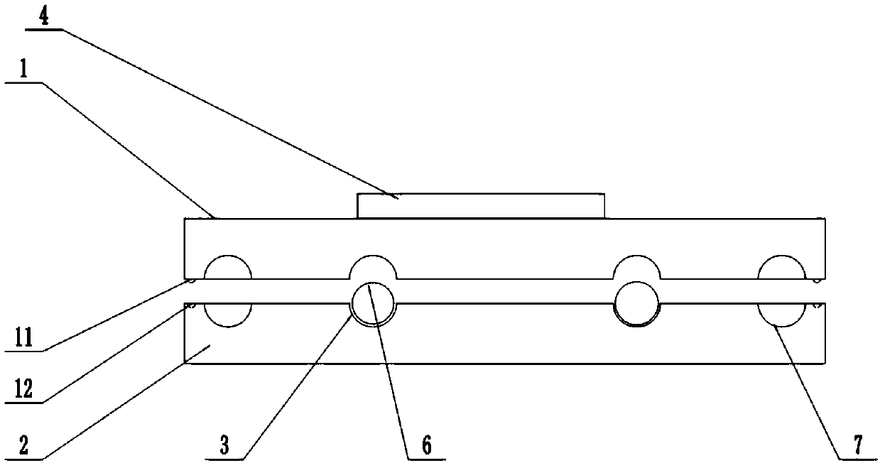
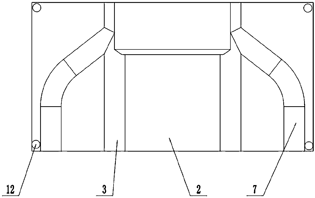
[0023] The orientation words such as "left, right" described in this embodiment are only limited to the appended figure 1 and figure 2 , a positioning tool for stamping, such as figure 1 As shown, the upper mold 1 and the lower mold 2 are included, and the power device for driving the upper mold 1 to move up and down is selected as the cylinder 5 in this embodiment, and the upper mold 1 and the lower mold 2 are equipped with a semicircular processing groove 7 in section. And chute 3, when the upper mold 1 and the lower mold 2 are engaged, the combination of the processing groove 7 and the cross section of the chute 3 is circular; as figure 2 As shown, the processing groove 7 intersects with the chute 3 at a certain angle, and the processing groove 7 is used to place and fix the workpiece. The chute 3 and the processing groove 7 are arranged symmetrically on both sides; the bolt at the end of th...

Embodiment 2

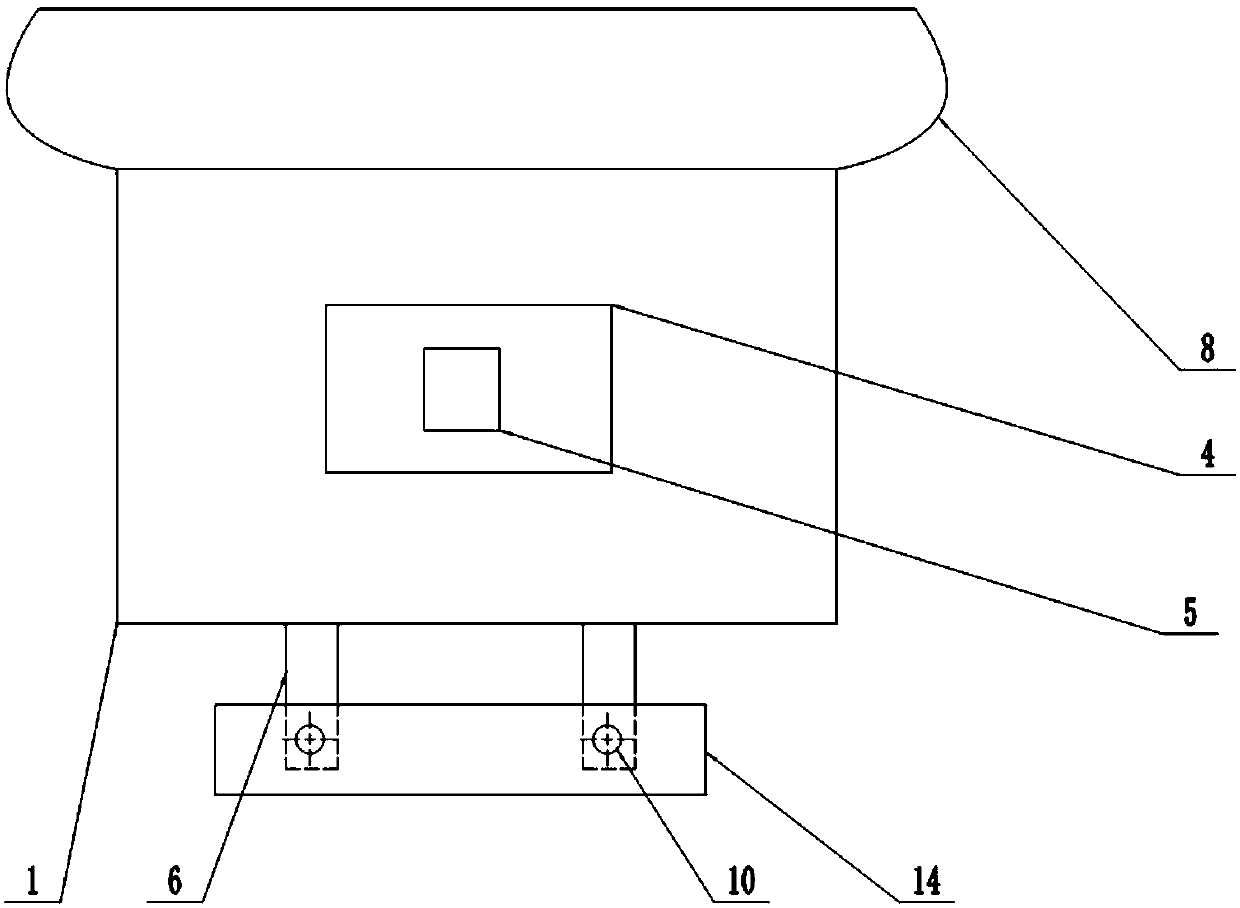
[0028] This embodiment increases the following on the basis of embodiment 1: as Figure 4 As shown, there is an air outlet pipe 9 connected to the cylinder 5, and the cylinder 5 drives the upper mold 1 to move upward and separate from the lower mold 2. During the separation process, the gas in the cylinder 5 is directed at the lower mold 2 through the air outlet of the air outlet pipe 9 for blowing treatment. like Figure 4 As shown, the lower die 2 is placed with a collection bag 8 in the downwind direction of the air flow; the gas can not only cool down the connecting rods that have just been stamped, facilitate the quick removal of the stamped connecting rods, but also accumulate the stamping process on the upper part of the lower die 2 Metal scraps are collected for disposal.


PUM


Abstract

The invention belongs to the field of machining, and particularly discloses a positioning tool for punching. The positioning tool comprises an upper mold and a lower mold, an air cylinder used for lifting is arranged on the top of the upper mold, the upper mold and the lower mold are each provided with a sliding groove with the section in a semi circular shape and a machining groove for placing the workpiece, the sliding groove of the lower mold is in sliding fit with a punching rod, the machining grooves and the sliding grooves are arranged in a crossed manner, and a punching rod can touch the machining parts in the machining grooves on the sliding paths of the sliding grooves. Through the technical scheme, the positioning tool for punching can punch the end faces of the machining parts into t he arc contact faces.

Description

technical field [0001] The invention belongs to the field of mechanical processing, and in particular relates to a positioning tool for stamping. Background technique [0002] Stamping forming is a common mechanical processing technology, mainly used for processing thin-walled parts. Common stamping tooling mainly includes a punch and a die. The punch is placed on the processing table, and the die is installed on the punching machine. During processing, the workpiece to be processed is placed on the punch, and then the punch drives the die to the punch. Move, so that the workpiece to be processed is pressed by the punch and the die to obtain a shaped stamped workpiece. [0003] However, in the stamping process, the concave die is punched vertically toward the punch in the horizontal direction, and the workpiece processed in the horizontal direction cannot be directly punched horizontally. In the processing or installation of the workpiece, when the shape of the rod end sur...

Claims


Application Information

Patent Timeline
IPC IPC(8): B21D22/02B21D37/10B21D37/16B21D43/00B08B5/02B08B15/04
CPCB08B5/02B08B15/04B21D22/02B21D37/10B21D37/16B21D43/003
Inventor 张斌
Owner BISHAN COUNTY ZONGHUI MACHINERY
Learn More