Eureka AIR delivers breakthrough ideas for toughest innovation challenges, trusted by R&D personnel around the world.

Diameter and pitch variable elbow equipment

A pipe bending equipment and variable pitch technology, which is applied in the field of pipe bending equipment, can solve the problems of pits and other problems on the surface of the pipe bending, and achieve the effect of ensuring stability

Active Publication Date: 2019-04-19
金惠伦管道科技(山东)有限公司
View PDF7 Cites 2 Cited by
  • Summary
  • Abstract
  • Description
  • Claims
  • Application Information

AI Technical Summary

Problems solved by technology

The invention is mainly used to solve the problem that the adjustment module on the pipe bending machine wears out pits on the surface of the pipe bend

Method used


Image

  • Diameter and pitch variable elbow equipment
  • Diameter and pitch variable elbow equipment
  • Diameter and pitch variable elbow equipment

Examples


Embodiment Construction

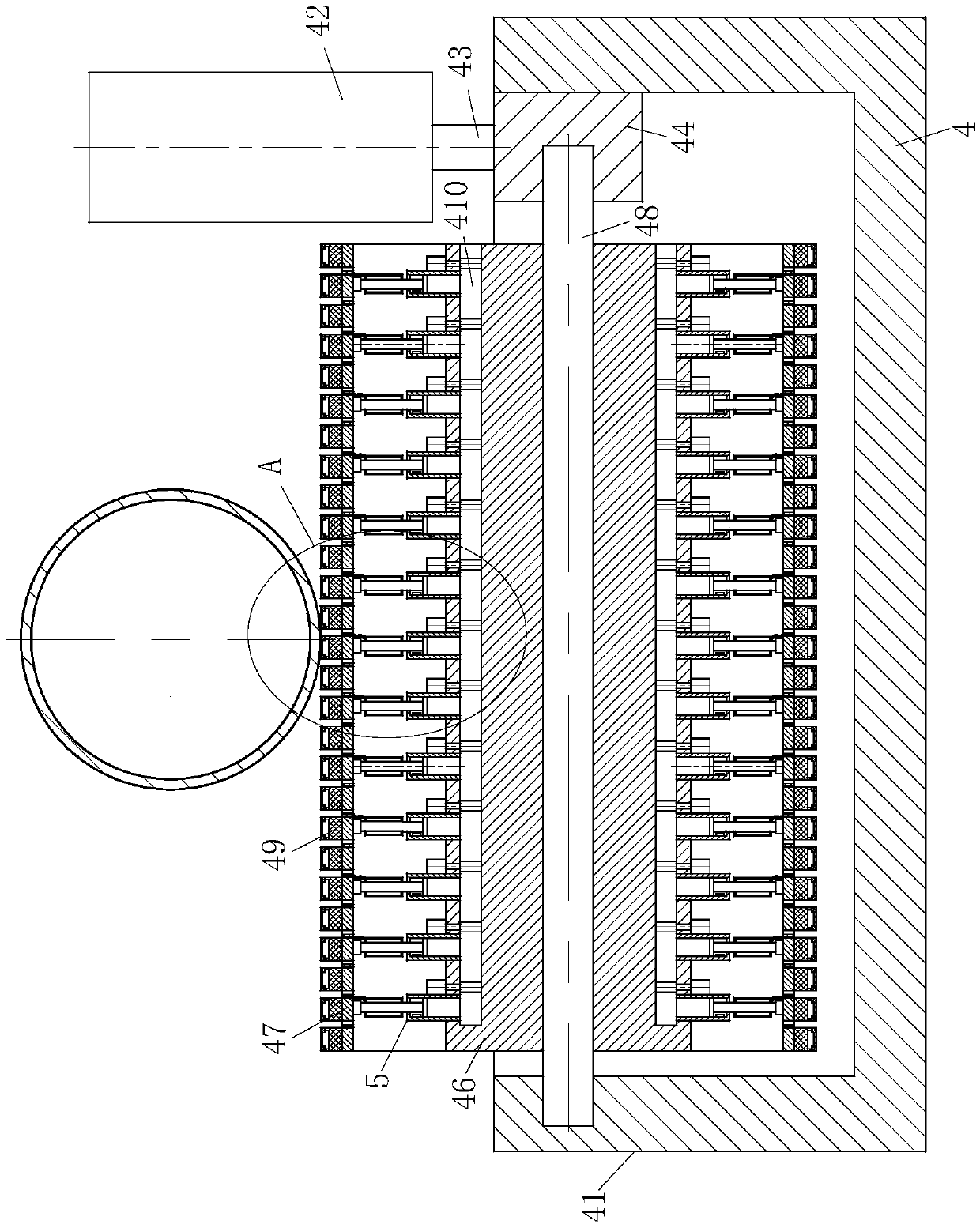
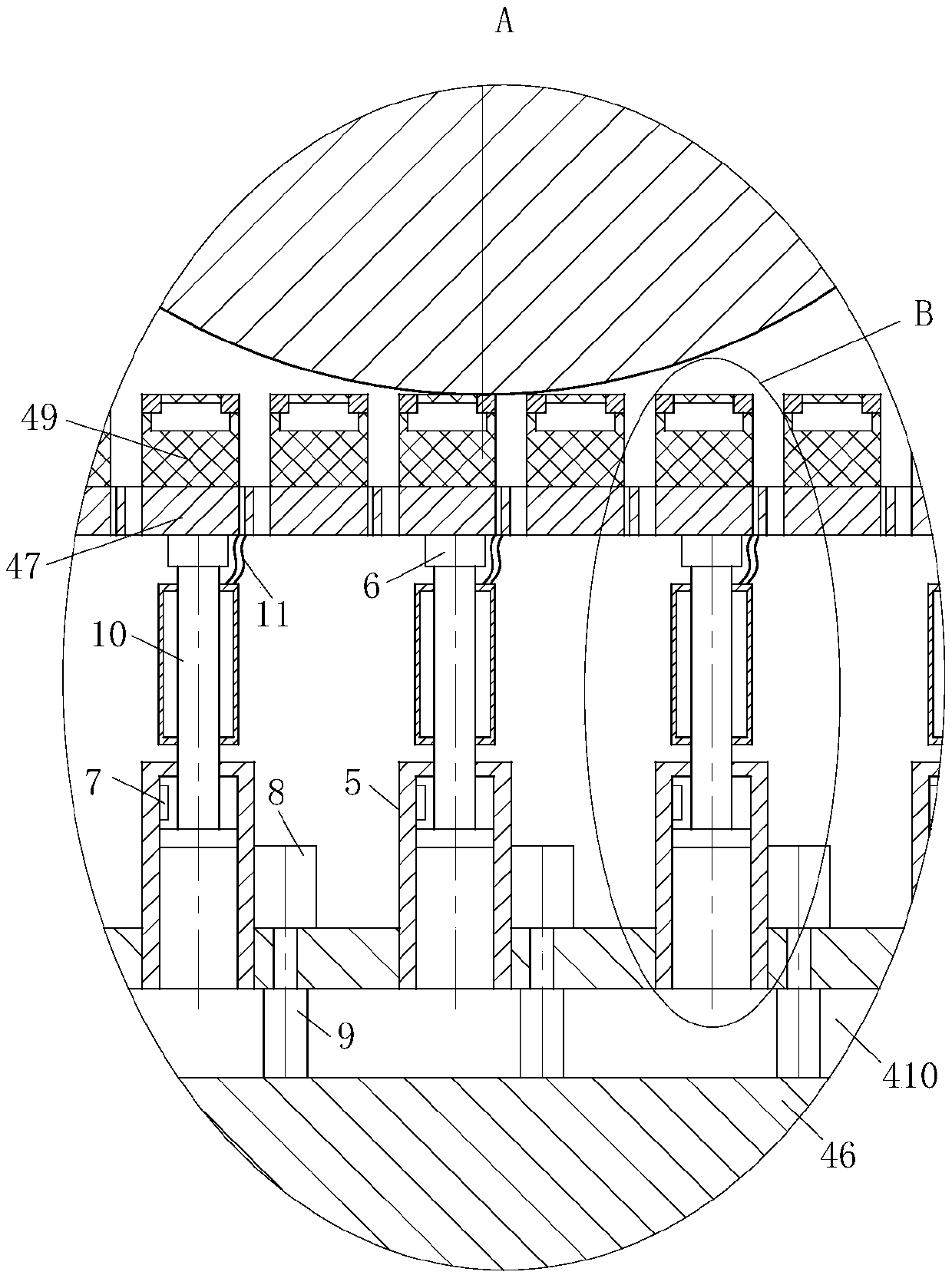
[0019] use Figure 1-Figure 4 A variable-diameter variable-pitch pipe bending equipment according to an embodiment of the present invention is described as follows.

[0020] Such as Figure 1-Figure 3As shown, a variable-diameter variable-pitch pipe bending equipment according to the present invention includes a first rotating roller 1, a second rotating roller 2 and a support roller 3. There are two first rotating rollers 1 horizontally, and two first rotating rollers Roller 1 is used to introduce the metal pipe, and there is a second roller 2 on the upper right of the two first rollers 1. The second roller 2 is used to bend the metal pipe. The first roller 1 and the second roller 2 There are two support rollers 3 on one side, the first rotating roller 1, the second rotating roller 2 and the supporting roller 3 are all driven by motors, and an adjustment module 4 is also included, and the adjustment module 4 is located at the middle position of the two supporting rollers 3 ...


PUM


Abstract

The invention belongs to the technical field of elbow equipment, and particularly relates to diameter and pitch variable elbow equipment. The diameter and pitch variable elbow equipment comprises twofirst rotating rollers, a second rotating roller and two supporting rollers, wherein the two first rotating rollers are horizontally arranged, the second rotating roller is arranged above the right ofthe two first rotating rollers, and the two supporting rollers are arranged on one sides of the first rotating rollers and the second rotating roller. The diameter and pitch variable elbow equipmentfurther comprise an adjusting module, and the adjusting module is located at the middle position of the two supporting rollers. The adjusting module comprises a supporting frame, a vertical adjustingroller and a transverse adjusting roller, wherein the transverse adjusting roller is rotationally connected with the supporting frame through a first rotating shaft, the upper right inner side wall ofthe supporting frame is fixedly connected with a fixing base, the top of the fixing base is rotationally connected with the vertical adjusting roller through a second rotating shaft, the vertical adjusting roller is located at one end of the transverse adjusting roller, the exterior of the transverse adjusting roller is provided with a metal cylinder, and the exterior of the metal cylinder is provided with a rubber cushion. The parts, located below hydraulic cylinders, in the transverse adjusting roller are provided with first cavities. The exterior of the supporting frame is provided with acontroller.

Description

technical field [0001] The invention belongs to the technical field of pipe bending equipment, in particular to pipe bending equipment with variable diameter and variable pitch. Background technique [0002] The bending pipe is bent by a complete set of bending equipment. The application range of the bending pipe is very wide. Hydraulic pipe bending machine, electric power construction, highway and railway construction, boiler, bridge, ship, furniture, decoration and other aspects of pipeline laying and repairing, has the advantages of multiple functions, reasonable structure, simple operation, convenient movement, fast installation, etc. The shape of the pipe is different. For the spiral pipe bend, the outer diameter and pitch of the pipe need to be changed during the manufacturing process. A special pipe bending machine is required to change the diameter and pitch of the pipe bend. On the pipe bender Generally, an adjustment module is set to change the outer diameter and ...

Claims


Application Information

Patent Timeline
IPC IPC(8): B21D7/08B21D7/16
CPCB21D7/08B21D7/16
Inventor 不公告发明人
Owner 金惠伦管道科技(山东)有限公司
Why Eureka
Eureka Blog
Learn More