
Oil fume waste gas treatment device for kitchen

A waste gas treatment device and oil fume technology, applied in the direction of oil fume removal, application, household stoves, etc., can solve the problems of oil fume purification pollution, difficulty in cleaning, and adhesion to the inner wall of the device, so as to slow down the flow speed and increase the contact area. Effect

Inactive Publication Date: 2019-04-16
深圳市唯绿农产品有限公司
View PDF7 Cites 1 Cited by
  • Summary
  • Abstract
  • Description
  • Claims
  • Application Information

AI Technical Summary

Problems solved by technology

The above-mentioned patents have the following deficiencies: 1. When purifying the oil fume, since the initial temperature of the oil fume is too high, the oil fume needs to be condensed and cooled, but this will cause the oil fume to flow back, which will affect the purification of the device ;2. When purifying the oil fume, due to the action of the exhaust machine, the oil fume will be quickly discharged from the pipeline, resulting in incomplete purification of the oil fume and polluting the external environment; 3. When purifying the oil fume, due to the oil fume It contains a lot of oil stains, which make the oil stains adhere to the inner wall of the device, making it difficult to clean the inner wall of the device after the device is purified

Method used


Image

  • Oil fume waste gas treatment device for kitchen
  • Oil fume waste gas treatment device for kitchen
  • Oil fume waste gas treatment device for kitchen

Examples


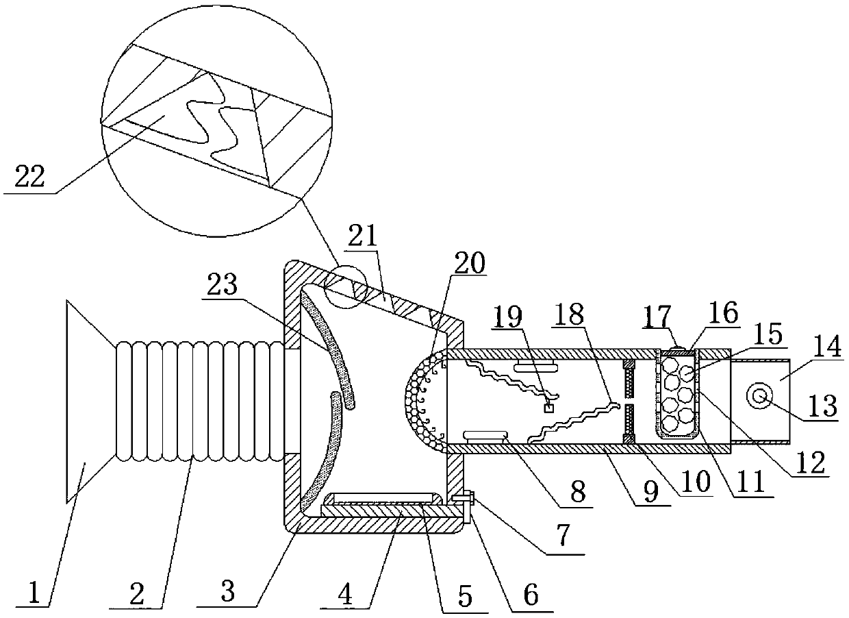
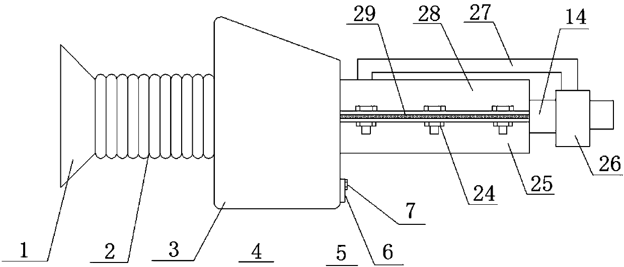
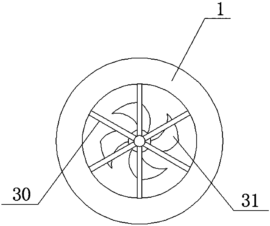
Embodiment Construction

[0027] The following will clearly and completely describe the technical solutions in the embodiments of the present invention with reference to the accompanying drawings in the embodiments of the present invention. Obviously, the described embodiments are only some, not all, embodiments of the present invention.

[0028] refer to Figure 1-5 , a cooking fume waste gas treatment device, comprising an air intake hopper 1, a placement frame 30 is welded on one side of the inner wall of the intake hopper 1, and an exhaust fan 31 is connected to one side of the outer wall of the placement frame 30 by bolts, and the air intake hopper 1 is welded with a fume pipe 2 on the inner wall of one side, and a treatment box 3 is welded on the outer wall of the oil fume pipe 2 away from the air intake hopper 1, and the inner wall of the side of the treatment box 3 is close to the top and the bottom. Sheet 23, the top outer wall of the processing box 3 has air inlets 21 distributed equidistantl...


PUM


Abstract

The invention discloses an oil fume waste gas treatment device for a kitchen. The oil fume waste gas treatment device for the kitchen comprises a gas inlet funnel; the inner wall of one side of the gas inlet funnel is provided with a placement frame; the outer wall of one side of the placement frame is provided with an exhaust fan; the inner wall of one side of the gas inlet funnel is provided with an oil fume pipe; one end, far away from the gas inlet funnel, of the outer wall of the oil fume pipe is provided with a treatment tank; the positions, close to the top and the bottom, of the innerwall of one side of the treatment tank are provided with fixed sheets respectively; the outer wall of the top of the treatment tank is provided with air inlets which are distributed at an equal interval; the inner walls of the two sides of each air inlet are provided with bulges respectively; the position, at the bottom, of the outer wall of one side of the treatment tank is provided with a rectangular hole; and a drawing plate is connected to the inner wall of the bottom of the rectangular hole in an inserting manner. The oil fume waste gas treatment device for the kitchen can prevent the phenomenon that oil fume is difficulty cleaned due to high temperature, can clean relatively large particle impurities in the oil fume, can retard the flowing speed of the oil fume and prevents the phenomenon that the device cannot timely perform purification treatment on the oil fume caused by too rapid flowing speed of the oil fume.

Description

technical field [0001] The invention relates to the technical field of waste gas treatment, in particular to a cooking fume waste gas treatment device. Background technique [0002] The cooking fume emitted by people when cooking is a large amount of thermal oxidation decomposition products produced by cooking oil and food under high temperature conditions. When cooking, the fat is heated. When the temperature of the edible oil is too high, blue smoke of initial decomposition will appear. As the temperature continues to rise, the decomposition speed of the edible oil will be accelerated, and a large amount of oily smoke will appear, accompanied by a pungent smell. , The emission of oily fume will pollute the external environment. In addition, oily fume will pose a threat to people's health, so it is necessary to control the oily fume in the kitchen. [0003] After retrieval, the Chinese patent authorization number is CN206222428U, which discloses a kind of oil fume purifica...

Claims


Application Information

Patent Timeline
Patent Type & Authority Applications(China)
IPC IPC(8): F24C15/20
CPCF24C15/2035
Inventor 韩燕
Owner 深圳市唯绿农产品有限公司
Learn More