Transportation device for battery pack of new energy vehicle

A technology for new energy vehicles and transportation devices, applied in transportation and packaging, trolleys, motor vehicles, etc., can solve the problems of troublesome unloading of battery packs, difficult to effectively fix, etc.

Inactive Publication Date: 2019-04-16
汤文志
View PDF0 Cites 0 Cited by
  • Summary
  • Abstract
  • Description
  • Claims
  • Application Information

AI Technical Summary

Problems solved by technology

[0003] The most important thing in a pure electric vehicle is the battery, and it is difficult to effectively fix the battery pack during transportation, and it is very troublesome to remove the battery pack

Method used


Image

  • Transportation device for battery pack of new energy vehicle
  • Transportation device for battery pack of new energy vehicle
  • Transportation device for battery pack of new energy vehicle

Examples


Embodiment

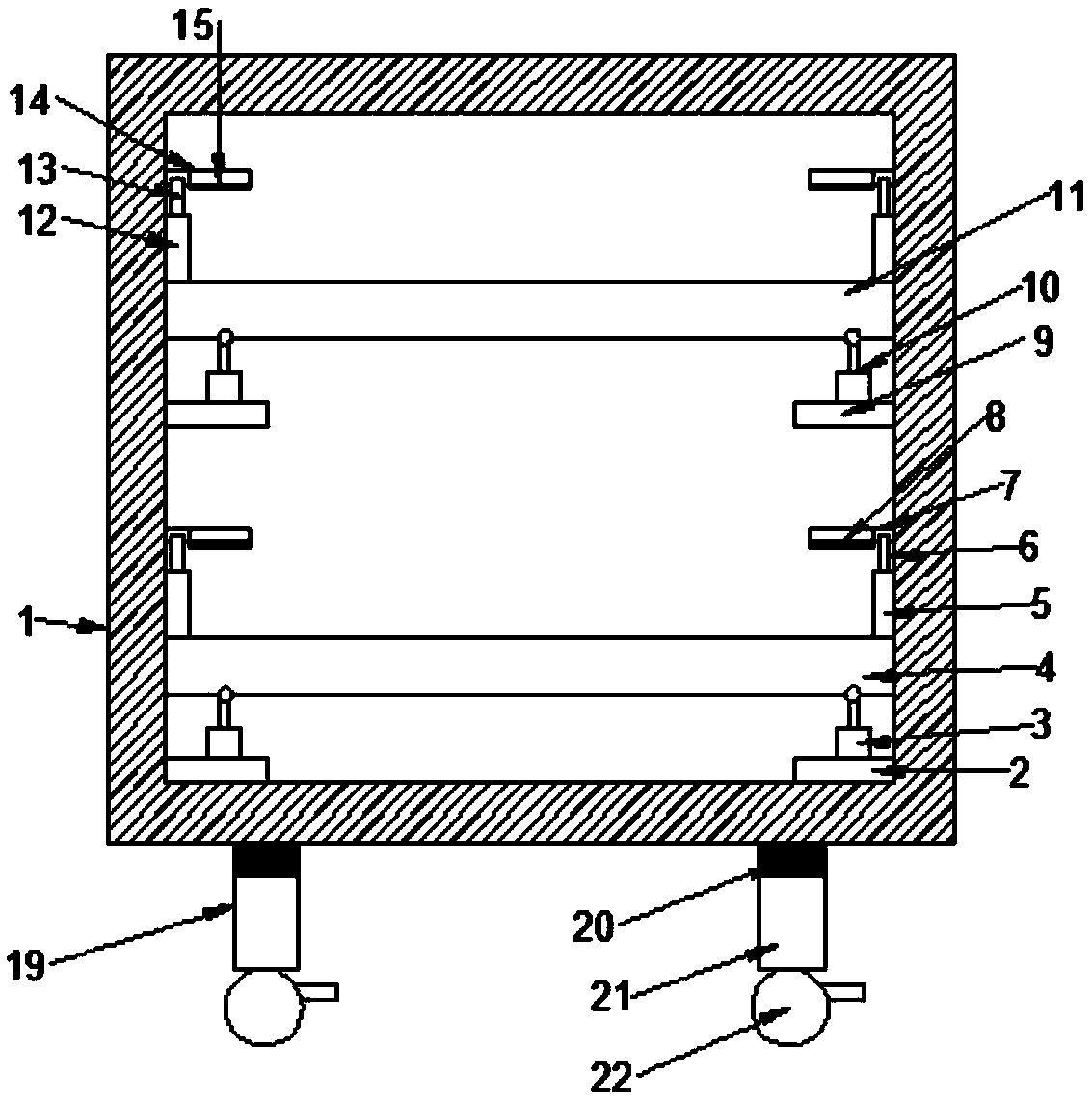
[0023] see Figure 1~2 , in an embodiment of the present invention, a transportation device for a battery pack of a new energy vehicle, comprising a casing 1, a first support plate 2, a first hydraulic cylinder 3, a second support plate 9 and a second object bearing plate 11, the The bottom of the housing 1 is symmetrically provided with a first support plate 2, the bottom of the first support plate 2 is fixedly connected with the inner surface of the bottom of the housing 1, and the top of the first support plate 2 is provided with a fixedly connected The first hydraulic cylinder 3, the upper end of the first hydraulic cylinder 3 is connected to the bottom front end of the first object receiving plate 4, and the first limiting plate fixedly connected is symmetrically arranged on both sides of the top of the first object receiving plate 4 5. The front and rear lengths of the first limiting plate 5 are the same as the front and rear lengths of the first object bearing plate 4; ...

Embodiment 2

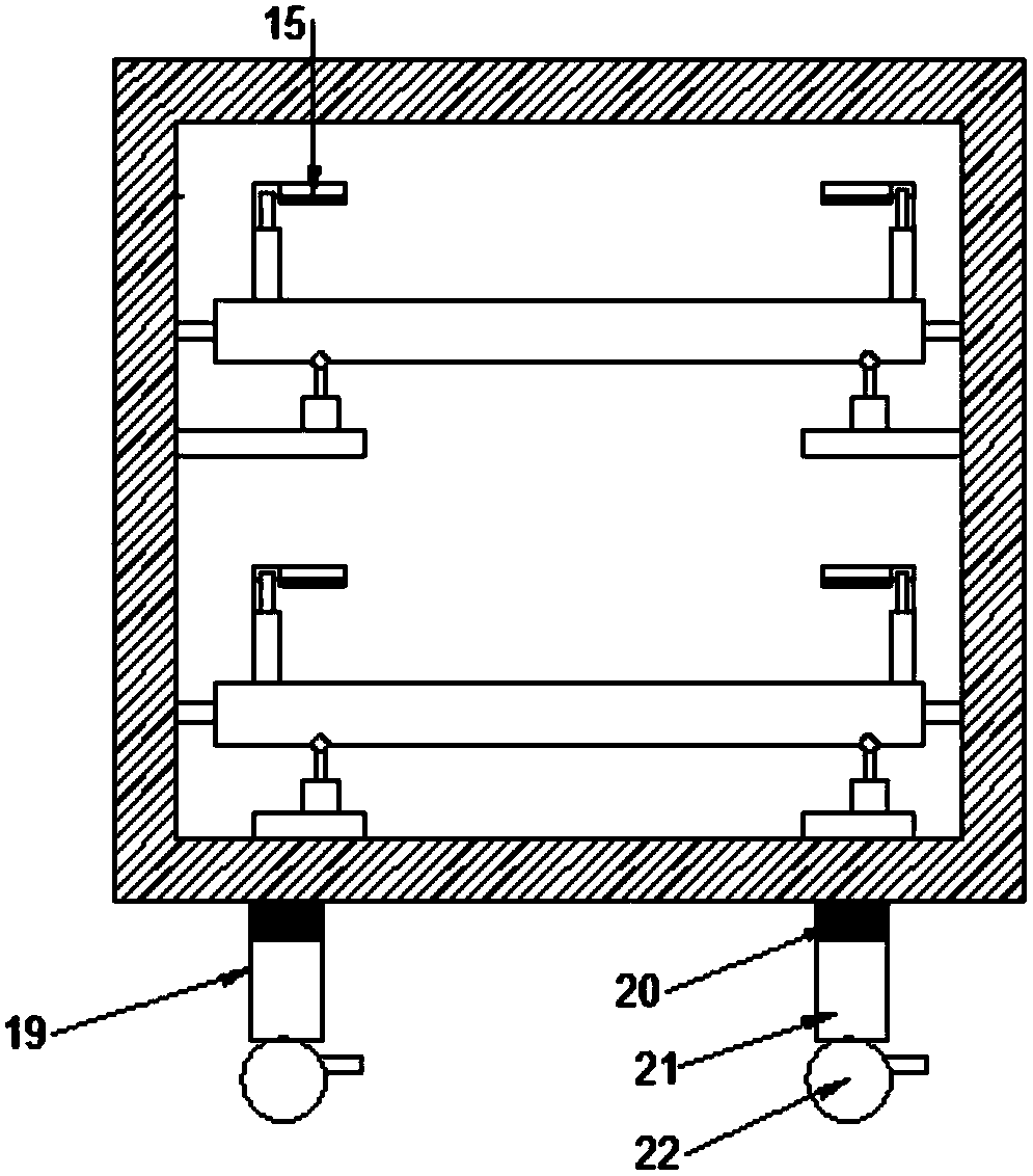
[0028] see Figure 3-4The difference between embodiment 2 and embodiment 1 is that the upper ends of the first hydraulic cylinder 3 and the second hydraulic cylinder 10 are respectively hinged with the bottom front sides of the first object plate 4 and the second object plate 11, and the The first hydraulic cylinder 3 and the second hydraulic cylinder 10 can be controlled up and down by the controller, and also include a connecting rod 23, a bearing 24, a hinge shaft 25, and the rear of the first object plate 4 and the second object plate 11 Both sides are connected with the inner surface of the rear wall of the housing 1 through the hinge shaft 25, and the middle of the outer surfaces of both sides of the first object bearing plate 4 and the second object bearing plate 11 are connected with the connecting rod 23, and the connecting rod 23 The other end of the shaft is connected with the bearing 24 in rotation, and the bearing 24 is fixedly connected with the inner surface of ...


PUM


Abstract

The invention discloses a transportation device for a battery of a new energy vehicle and relates to the field of new energy vehicles. The problem is mainly solved that in the transportation process of the new energy battery, the new energy battery is easy to move and inconvenient to unload. The device comprises a shell, first supporting plates, first hydraulic cylinders, second supporting platesand second bearing plates, the first supporting plates are left and right symmetrically arranged at the bottom of the shell, and the bottoms of the first supporting plates are fixedly connected with the inner surface of the bottom of the shell; the first hydraulic cylinders fixedly connected are arranged at the tops of the first supporting plates, and the upper ends of the first hydraulic cylinders are connected with the front ends of the bottoms of the first bearing plates; fixedly-connected first limit plates are symmetrically arranged at the two sides of the top of each first bearing plate,and the front-rear length of the first limit plates is identical to that of the first bearing plates; first rotation rods are arranged at the upper ends of the first limit plates. According to the transportation device, the battery pack can be effectively fixed, the buffer protection function is achieved, and multiple battery packs can be fixed at the same time.

Description

technical field [0001] The invention relates to the field of new energy vehicles, in particular to a transportation device for a new energy vehicle battery pack. Background technique [0002] With the continuous development and progress of society, cars have become an irreplaceable means of transportation in people's lives, and the air pollution caused by cars is also a headache for every country; and the emergence of new energy vehicles has solved this problem brought the dawn. New energy vehicles include pure electric vehicles, extended-range electric vehicles, hybrid vehicles, fuel cell electric vehicles, hydrogen engine vehicles, and other new energy vehicles. A pure electric vehicle is a vehicle that uses a single battery as the energy storage power source. It uses the battery as the energy storage power source, and supplies electric energy to the motor through the battery to drive the motor to run, thereby driving the car. [0003] The most important thing in a pure ...

Claims


Application Information

Patent Timeline
IPC IPC(8): B62B3/04
CPCB62B3/04B62B2202/61B62B2203/07B62B2203/60
Inventor 汤文志
Owner 汤文志
Why Eureka
Try Eureka