A device and method capable of improving coil strength and electromagnetic forming efficiency

An electromagnetic forming and coil strength technology, applied in the field of electromagnetic pulse forming, can solve problems such as low coil strength, energy loss, and coil failure, and achieve the effects of improving forming efficiency, suppressing deformation, and increasing coil strength

Active Publication Date: 2021-01-26
CENT SOUTH UNIV
View PDF7 Cites 0 Cited by
  • Summary
  • Abstract
  • Description
  • Claims
  • Application Information

AI Technical Summary

Problems solved by technology

[0003] However, the current electromagnetic forming technology still cannot be applied on a large scale in industry, mainly because: (1) only a small part of the energy is used for the plastic deformation of the workpiece in the electromagnetic pulse forming process, and most of the energy is leaked in the form of magnetic field and thermal energy. For example, in the document "3D modeling and deformation analysis for electromagnetic sheet forming process", it is mentioned that the energy utilization rate of sheet electromagnetic forming is 3.73%; (2) The coil strength is low
Electromagnetically formed coils are wound (or wire-cut) by metal wires into a certain shape, and then the wound metal is packaged with insulating materials. The production process of the size coil is: firstly engrave grooves on the whole epoxy board, then embed the wire-cut conductors into the epoxy board, and finally cure with epoxy resin and vacuumize (the structure and stress of the formed coil are as follows: attached Figures 1 to 3 shown), but compared with metal materials, the strength of insulating materials is low, and the coil often deforms during the discharge process, resulting in coil failure. For example, in the document "Materials formability and coil design in electromagnetic forming", Golovashchenko mentioned that the failure of the coil is mainly Because the wire is deformed by force, the insulating layer around it is broken; (3) large-sized coils often have large inductance, and the first half-wave time of the current after discharge exceeds the termination time of sheet metal deformation, resulting in loss of magnetic field energy (existing coil structure The corresponding pulse current curve through the coil wire is as attached Figure 10 shown in ① and ②)

Method used


Image

  • A device and method capable of improving coil strength and electromagnetic forming efficiency
  • A device and method capable of improving coil strength and electromagnetic forming efficiency
  • A device and method capable of improving coil strength and electromagnetic forming efficiency

Examples


Embodiment 1

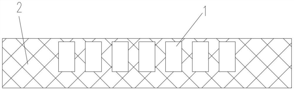
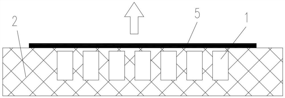
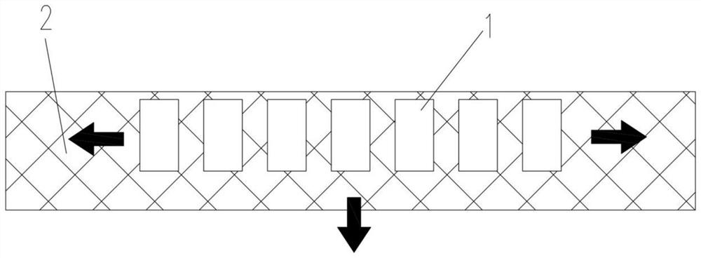
[0038] Such as Figure 4 As shown, a device that can improve coil strength and electromagnetic forming efficiency includes a coil metal wire 1, an insulator 2 and a metal groove 3, the coil metal wire 1 is embedded in the metal groove 3, and the insulator 2 is filled in the coil metal wire 1 In the gap between the metal groove 3 and the metal groove 3, the metal workpiece 5 to be formed is placed above the coil metal wire 1.

[0039] In this embodiment, the metal groove 3 is a continuous integral structure, and the coil metal wire 1 is placed in the metal groove 3 .

[0040] In this embodiment, the coil metal wire 1 is a single-layer structure of metal block wire cutting or wire winding.

[0041] In this embodiment, the electrical conductivity of the metal groove 3 is 1e-8˜1e-6 s / m.

[0042] In this embodiment, the height of the metal groove 3 is greater than that of the insulator 2 .

[0043] A method that can improve coil strength and electromagnetic forming efficiency, u...

Embodiment 2

[0047] Such as Figure 5 As shown, the difference between the device of this embodiment and the device of Embodiment 1 is that in this embodiment, the height of the metal groove 3 is lower than that of the insulator 2, and the rest of the structure and forming method are the same as in Embodiment 1.

Embodiment 3

[0049] Such as Figure 6 As shown, the difference between the device of this embodiment and the device of Embodiment 1 is that in this embodiment, the height of the metal groove 3 is flush with the height of the insulator 2, and the coil metal wire 1 is wire-cut or wound from a metal block. The multilayer coil structure, all the other structures and forming method are the same as embodiment 1.


PUM


Abstract

The invention discloses a device capable of improving coil strength and electromagnetic forming efficiency, which comprises a coil metal wire, an insulator and a metal groove, the coil metal wire is embedded in the metal groove, and the insulator is filled in the coil metal wire and the metal groove. In the gap between the grooves, the metal workpiece to be formed is placed above the coil metal wire; an electromagnetic forming method is also disclosed, which includes the following steps: 1) according to the forming requirements, the coil metal wire is wound or wire-cut into A specific shape, and the coil metal wire is embedded in the metal groove, and the space between the coil metal wire and the metal groove is filled with an insulator by adding insulating material to the gap between the coil metal wire and the metal groove; 2) The metal workpiece to be formed is placed on the coil metal wire, and the coil metal wire is energized to carry out the electromagnetic pulse forming process. The invention can not only greatly improve the electromagnetic forming efficiency, but also improve the strength of the coil.

Description

technical field [0001] The invention relates to the technical field of electromagnetic pulse forming for plastic forming of materials, in particular to a device and method capable of improving coil strength and electromagnetic forming efficiency. Background technique [0002] Electromagnetic pulse forming is a method of high-speed machining of metal workpieces using pulsed magnetic field force. The research shows that under high-speed impact, the material produces a dynamic behavior different from the quasi-static deformation behavior of the traditional processing method, that is, the material appears crystal twinning, tissue phase transformation, and adiabatic shear under the impact of deformation elastic waves and plastic waves. isodynamic behavior. Therefore, it can effectively improve the forming limit of hard-to-deform materials such as aluminum alloys, magnesium alloys and titanium alloys, and reduce springback. [0003] However, the current electromagnetic forming t...

Claims


Application Information

Patent Timeline
Patent Type & Authority Patents(China)
IPC IPC(8): B21D26/14
CPCB21D26/14
Inventor 崔晓辉张志武喻海良杜志浩邱东阳
Owner CENT SOUTH UNIV
Why Eureka
Try Eureka