
Device for separating waste concrete to manufacture sand, stone and silicate aluminate material

A technology for waste concrete and aluminosilicate, applied in solid waste management, sustainable waste treatment, cleaning methods and utensils, etc., can solve the problems of low energy consumption, low heat rate, emission, low efficiency, etc. Natural environment, solving the shortage of admixture sources, the effect of simple process and equipment

Pending Publication Date: 2019-04-16
长沙紫宸科技开发有限公司
View PDF13 Cites 4 Cited by
  • Summary
  • Abstract
  • Description
  • Claims
  • Application Information

AI Technical Summary

Problems solved by technology

[0006] CN200510136624.7 Waste concrete activation regeneration cement technology, CN201510399575.X method of processing waste concrete with rotary kiln to make active slag powder and active aggregate, CN201510399659.3 A method of using shaft kiln to process waste concrete to make active slag powder and aggregate method, CN201510399419.3 a method for making ecological cement and activated sand from waste concrete and sludge, and CN201520493211.3 a system for making active slag powder and aggregate from waste concrete, which provides an industrial kiln for crushing the broken particles Material heat treatment, dehydration, loosening or decomposition of the cement gelling components that bind the sand and gravel together, and then use a ball mill to remove the structural defects such as cement minerals and soft tissues on the surface of the sand and gravel particles, and then separate to obtain recycled aggregate sand Although the above-mentioned method can obtain high-quality recycled sand, stone aggregates and activated cement stone materials, there are the following problems: one needs to carry out heat treatment, consumes fuel, and the combustion of fuel and the decomposition of limestone aggregates produce air pollution and a large amount of Second, it needs to be ground by a ball mill with high energy consumption and low heat rate, which has high power consumption, low efficiency, and produces secondary pollution; moreover, the investment is relatively large, and it is not suitable for waste concrete with a large amount and a wide area. Low investment, low cost local centralized processing

Method used


Image

  • Device for separating waste concrete to manufacture sand, stone and silicate aluminate material
  • Device for separating waste concrete to manufacture sand, stone and silicate aluminate material
  • Device for separating waste concrete to manufacture sand, stone and silicate aluminate material

Examples


Embodiment 1

[0026] refer to figure 1 , this embodiment includes a disintegration repairing device 1, a separation device 2, an inspection and discharge mechanism 3, a high-pressure water system 5 and a bracket 6, and the mixing of the discharge port 110 of the disintegration repairing device 1 and the separation device 2 The material inlet 25 is connected, the maintenance and discharge mechanism 3 is fixed on the disintegrating material repairing device 1, the high-pressure water system 5 is connected with the disintegrating material repairing device 1 and the separation device 2 respectively, and the disintegrating repairing material The device 1 and the separation device 2 are fixed on the bracket 3 .

[0027] The disintegration and repairing device 1 described therein is a first-stage centrifugal impact grinding disintegration and repairing mechanism, and the first-stage centrifugal impact grinding disintegration and repairing mechanism mainly includes a bracket 11, a cylinder body 12,...

Embodiment 2

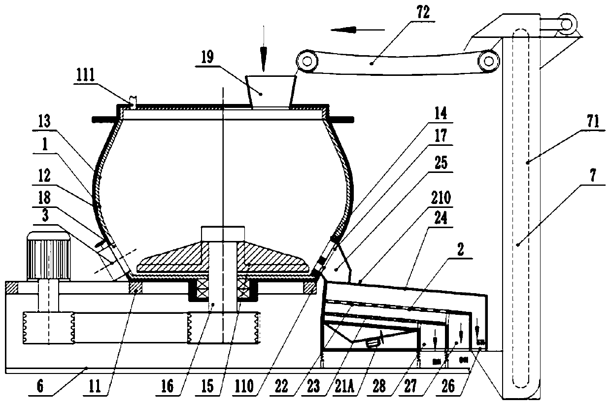
[0030] refer to figure 2 , this embodiment adopts the form of a dry-type primary disintegration and repairing material mechanism, mainly including a disintegration and repairing device 1, a separation device 2, an inspection and discharge mechanism 3, a power mechanism 4, a material circulation system 7 and a bracket 6, the described The discharge port 110 of the disintegrating material repairing device 1 is connected with the feed port 25 of the separation device 2, the maintenance and discharge mechanism 3 is fixed on the disintegrating material repairing device 1, and the inlet and outlet of the material circulation system 7 are respectively connected with the The stone discharge port 26 of the separation device 2 is connected to the feed port 19 of the disintegration and repair device 1; the disintegration and repair device 1, the separation device 2, and the material circulation system 7 are fixed on the support 3.

[0031] The disintegration and repairing device 1 descr...

Embodiment 3

[0033] refer to image 3 , this embodiment adopts three-stage wet disintegration and repair mechanism, including disintegration and repair mechanism 1, disintegration and repair mechanism 1IA, disintegration and repair mechanism II1B, separation device 2, maintenance and discharge mechanism 3, power mechanism 4, High pressure water system 5, support 6.

[0034] The disintegration and repairing mechanism 1, the disintegration and repairing mechanism 1IA, and the disintegration and repairing mechanism II1B constitute a disintegration and repairing device; the disintegration and repairing mechanism 1 mainly includes a bracket 11, a cylinder 12, a wear-resistant Lining plate 13, overflow grate plate 14, a wear-resistant impeller 15 throwing tray, main shaft 16, overflow hole 17, discharge port 18, feed port 19, discharge port 110, cylinder 12 is fixed on the bracket 11 Above, the wear-resistant liner 13 is fixed on the inner wall of the cylinder 12, the wall of the cylinder 12 is...


PUM

PropertyMeasurementUnit
particle diameteraaaaaaaaaa

Abstract

The invention relates to a device for separating waste concrete to manufacture sand, stone and silicate aluminate material. The device comprises a disintegrating and repairing device, a separating device and a bracket; a material outlet of the disintegrating and repairing device communicates with a material inlet of the separating device; and the disintegrating and repairing device and the separating device are fixedly arranged on the bracket. The device is simple and has simple process, little land occupation, little investment, and effective and high-efficiency disintegration; the device canbe promoted to recycling of the waste concrete, and is beneficial to protecting the social ecological environment and the natural environment and beneficial to promoting employment opportunities; andmeanwhile the device can achieve the effective resource recycling of the three original constituent materials (sand, stone, binder) in the waste concrete and can greatly reduce the consumption of limestone, clay and shale of the limited natural resources during the cement production for the economic construction.

Description

technical field [0001] The invention relates to the technical field of environmental protection equipment, in particular to a device for separating waste concrete into sand, stone and aluminosilicate materials. Background technique [0002] As we all know, inorganic building materials, especially commonly used concrete, mortar, and cement bricks, are mainly composed of composite building materials in which cementitious materials, sand materials, and / or stone materials are solidified together. The scale of my country's infrastructure is huge, and the huge amount of construction projects across the country requires a large amount of sand, stone and cement raw materials. The mining and supply of sand and stone raw materials required by the huge infrastructure scale will continue to have an irreversible impact on the environment; at the same time, The production of a large amount of cement needed for engineering construction continues to consume high energy consumption and high p...

Claims


Application Information

Patent Timeline
Patent Type & Authority Applications(China)
IPC IPC(8): B02C13/18B02C13/282B02C13/286B02C13/30B02C23/10B08B3/02C04B20/02C04B7/24C04B18/16
CPCC04B7/246C04B20/026B02C13/1807B02C13/185B02C13/282B02C13/286B02C13/30B02C23/10B08B3/02B02C2201/06B02C2013/2825B02C2013/28609C04B18/16Y02P40/10Y02W30/91
Inventor 尹小林韩建英
Owner 长沙紫宸科技开发有限公司
Learn More