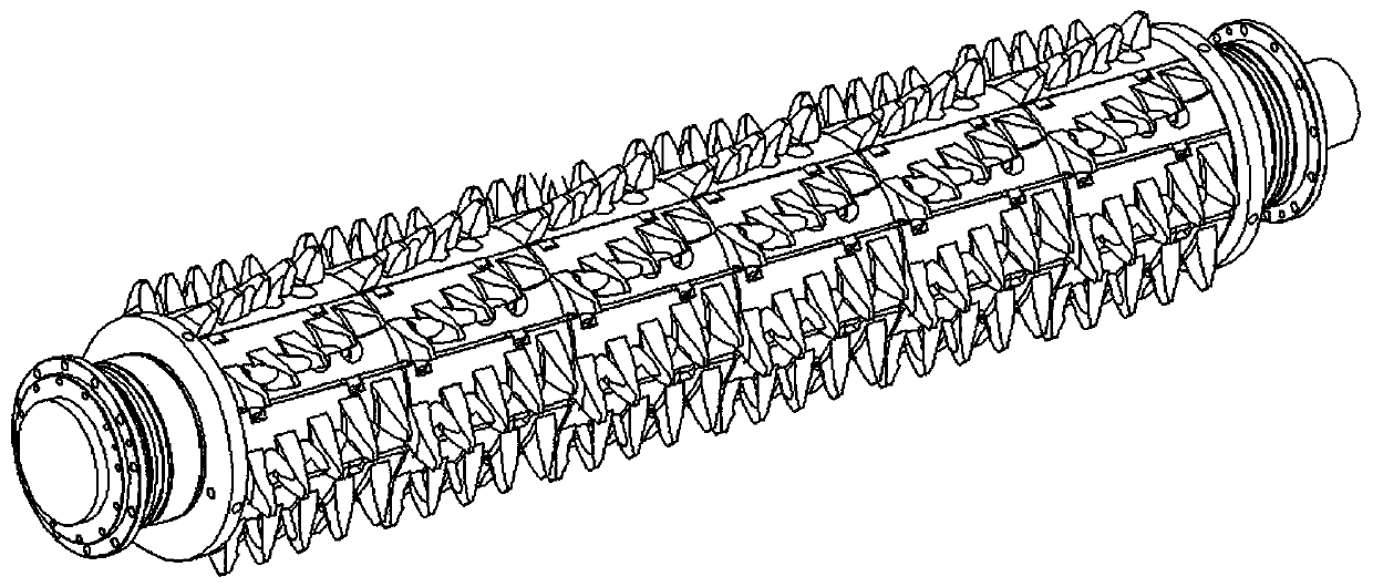
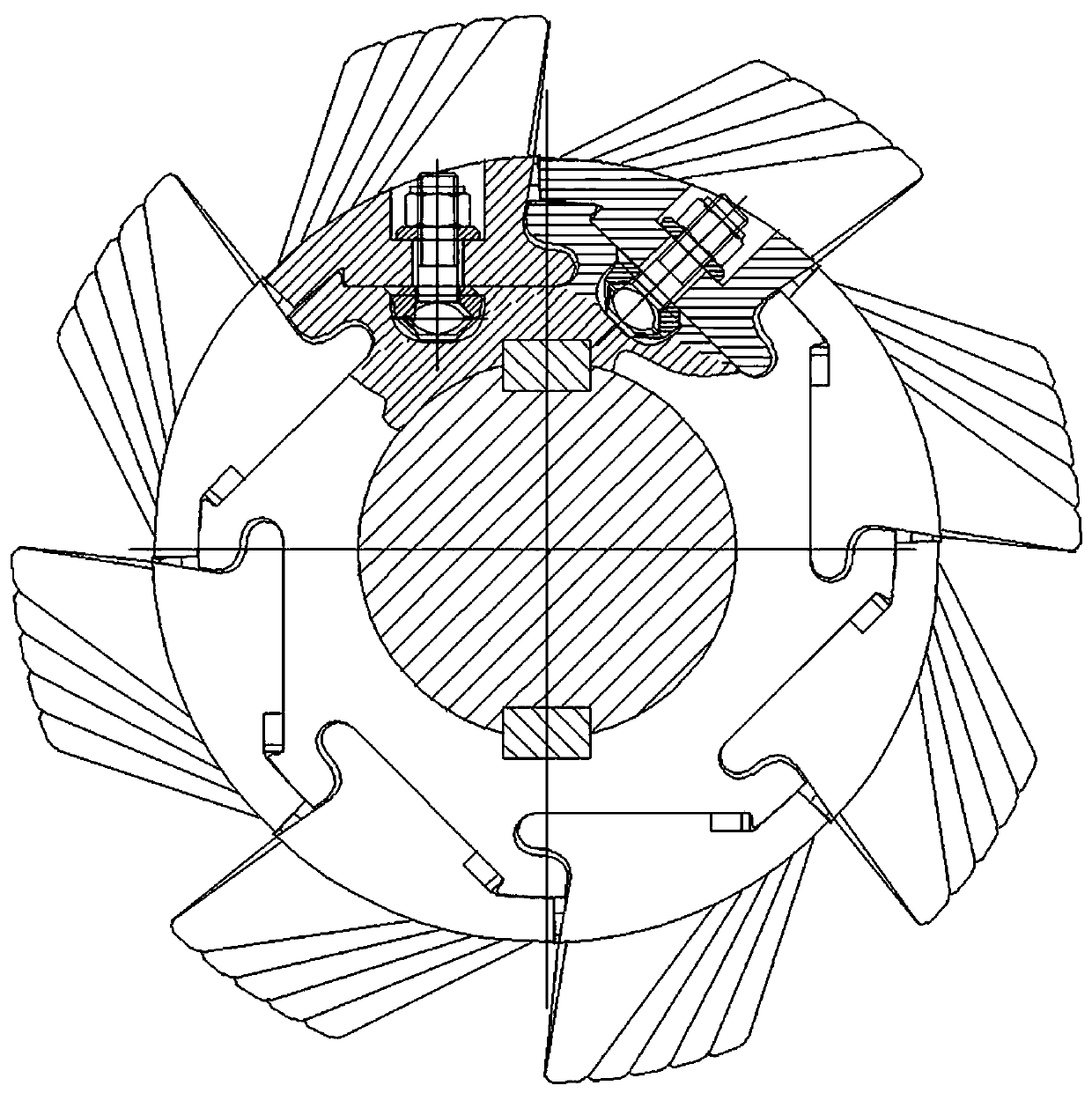
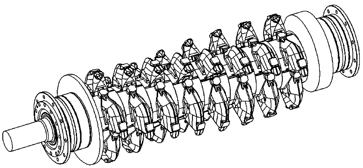
Tooth roller structure of double-tooth-roller type power crusher
A technology of crusher and double-toothed rollers, which is applied in the direction of grain processing, etc., can solve the problems of large amount of fixing bolts, easy thread removal of nuts, and low discharge efficiency, so as to reduce equipment maintenance, improve stability and reliability, and improve The effect of discharge efficiency
- Summary
- Abstract
- Description
- Claims
- Application Information
AI Technical Summary
Problems solved by technology
Method used
Image

Examples
Embodiment Construction
[0034] In order to make the technical means, creative features, goals and effects achieved by the present invention easy to understand, the present invention will be further elaborated below in conjunction with specific embodiments:
[0035] Therefore, the following detailed description of the embodiments of the present invention provided in the accompanying drawings is not intended to limit the scope of the claimed invention, but only represents selected embodiments of the present invention, based on the embodiments of the present invention, All other embodiments obtained by persons of ordinary skill in the art without creative efforts fall within the protection scope of the present invention.
[0036] It should be noted that like numerals and letters denote similar items in the following figures, therefore, once an item is defined in one figure, it does not require further definition and explanation in subsequent figures.
[0037] The terms "first", "second", "third", etc. a...
PUM
 Abstract
Description
Claims
Application Information
 - R&D
- Intellectual Property
- Life Sciences
- Materials
- Tech Scout
- Unparalleled Data Quality
- Higher Quality Content
- 60% Fewer Hallucinations
Browse by: Latest US Patents, China's latest patents, Technical Efficacy Thesaurus, Application Domain, Technology Topic, Popular Technical Reports.
© 2025 PatSnap. All rights reserved.Legal|Privacy policy|Modern Slavery Act Transparency Statement|Sitemap|About US| Contact US: help@patsnap.com