Photoacoustic microscopic imaging device

An imaging device, photoacoustic microscopy technology, applied in medical science, sensors, diagnostic recording/measurement, etc., can solve the problem of lower detection sensitivity, resolution, image signal-to-noise ratio, poor photoacoustic coaxial time and other issues, to achieve the effect of reducing the experimental time cost, optimizing the photoacoustic confocal adjustment, and improving the experimental efficiency

Pending Publication Date: 2019-04-16
SHENZHEN INST OF ADVANCED TECH
View PDF0 Cites 2 Cited by
  • Summary
  • Abstract
  • Description
  • Claims
  • Application Information

AI Technical Summary

Problems solved by technology

Traditional probes lack high-precision adjustable functions, and the photoacoustic coaxial confocal effect is poor, which reduces the detection sensitivity, resolution, and image signal-to-noise ratio of the high-resolution photoacoustic microscopy imaging system; the operation is complicated and time-consuming, increasing The cost of experiment time is reduced; the stability is poor, which has a great impact on the continuity of the continuous monitoring experiment process and the accuracy of the results

Method used


Image

  • Photoacoustic microscopic imaging device
  • Photoacoustic microscopic imaging device
  • Photoacoustic microscopic imaging device

Examples


Embodiment Construction

[0026] In order to make the object, technical solution and advantages of the present invention clearer, the present invention will be further described in detail below in conjunction with the accompanying drawings and embodiments. It should be understood that the specific embodiments described here are only used to explain the present invention, not to limit the present invention.

[0027] It should be noted that the terms "setting" and "connecting" should be understood in a broad sense, for example, they can be directly set and connected, or indirectly set and connected through a central component or a central structure.

[0028] In addition, if there are "longitudinal", "transverse", "length", "width", "thickness", "upper", "lower", "front", "rear", "left", " Terms such as "right", "vertical", "horizontal", "top", "bottom", "inner", "outer", etc. indicate the orientation or positional relationship, which are based on the orientation or positional relationship shown in the dr...


PUM


Abstract

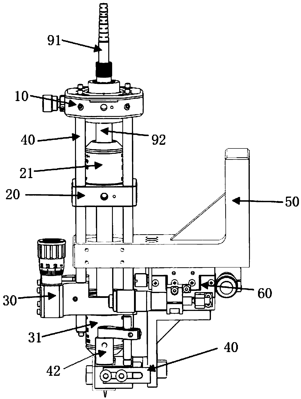
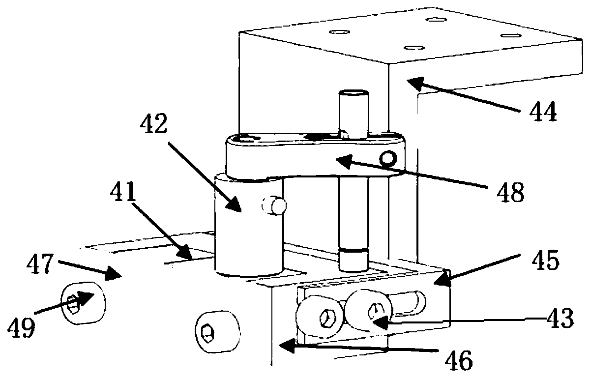
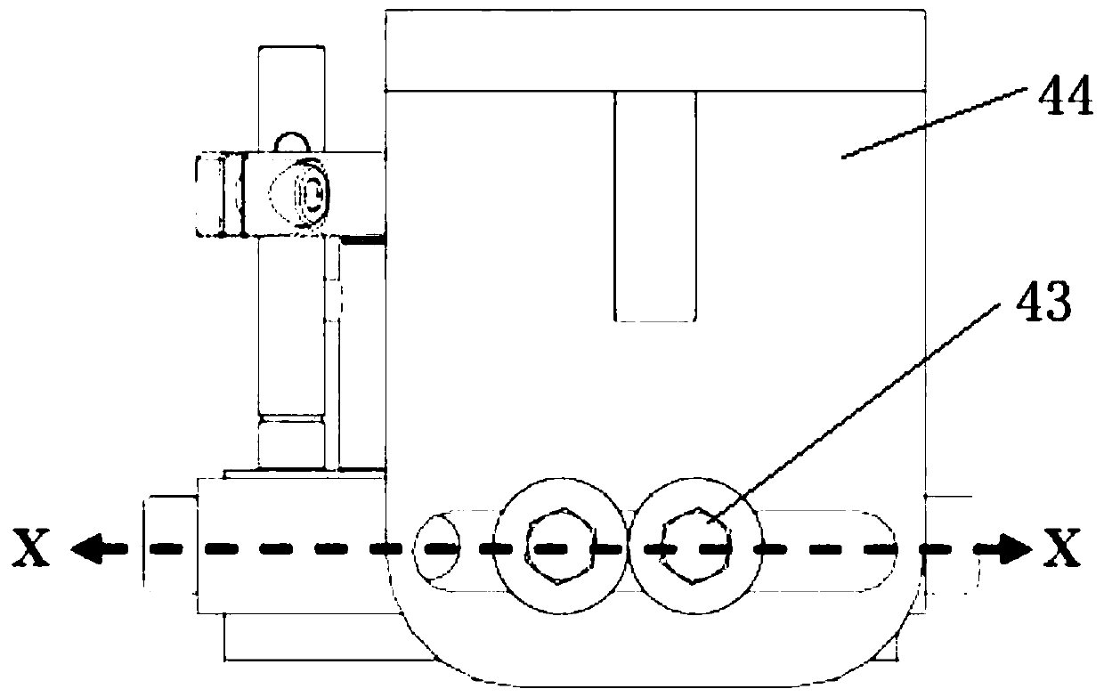
The invention relates to the technical field of microscopic imaging, and discloses a photoacoustic microscopic imaging device, which comprises a translation mounting seat, a cage plate and a Z-axis adjusting mounting seat which are connected by adopting a cage type coaxial system, wherein the translation mounting seat is provided with an optical fiber position adjusting structure which can be adjusted in X, Y and Z directions; a photoacoustic prism clamp is arranged below the Z-axis adjusting mounting seat, the photoacoustic prism clamp is provided with a photoacoustic prism group and an ultrasonic transducer, and the photoacoustic prism clamp is provided with a photoacoustic prism position adjusting structure. According to the photoacoustic microscopic imaging device, the stable cage typecoaxial system is adopted to enable a probe optical element to be installed in a common optical axis, a three-dimensional precision adjusting device is arranged to facilitate adjusting the alignmentand focus of the optical path of the probe, meanwhile,a clamping and adjusting device of the photoacoustic prism is designed, the photoacoustic coaxial confocal adjustment is optimized, the system sensitivity, the imaging resolution and the signal-to-noise ratio are improved, the adjustment is convenient, the experiment efficiency is improved, and the experiment time cost is reduced.

Description

technical field [0001] The invention belongs to the technical field of microscopic imaging, in particular to a photoacoustic coaxial and confocal photoacoustic microscopic imaging device. Background technique [0002] Photoacoustic imaging technology (PAT), its principle is mainly based on the photoacoustic effect, that is, after a substance absorbs modulated light or pulsed light, part of the light energy is converted into heat energy. Due to the thermoelastic effect, the substance expands and periodically expands with heat and contracts with cold. Generate ultrasound. The photoacoustic conversion phenomenon was discovered by American scientist Bell in 1880, and this physical phenomenon was called "photoacoustic effect". It was not until the 1970s that the photoacoustic effect began to be applied in biomedicine. In the 1990s, with the improvement of the solid-state photoacoustic theory and the development of laser and ultrasonic detection technologies, the photoacoustic ef...

Claims


Application Information

Patent Timeline
IPC IPC(8): A61B5/00
CPCA61B5/0095
Inventor 刘成波陈宁波张建辉王柏权刘良检
Owner SHENZHEN INST OF ADVANCED TECH
Why Eureka
Try Eureka