
An ultra-thin plastic-coated iron mold with a mesh structure and its application method

A pore structure, ultra-thin technology, applied in the direction of coating, etc., can solve the problems of immaturity, yield decline, etc., to achieve the effect of improving stability, increasing yield, and improving accuracy

Active Publication Date: 2020-12-29
东莞市巨成模具有限公司
View PDF3 Cites 0 Cited by
  • Summary
  • Abstract
  • Description
  • Claims
  • Application Information

AI Technical Summary

Problems solved by technology

[0002] With the advancement of modern technology, displays are an indispensable product in modern life. The back shells of most displays in the market are usually made of plastic integral injection molding. The advantages of the injection molding method are fast production speed, High efficiency, automatic operation, various designs and colors, simple to complex shapes, large to small sizes, accurate product size, easy replacement of products, and the ability to form a variety of complex parts, and the existing The display case manufacturing mold in the technology, the technology of the hot runner system used in the technology is not yet mature, resulting in excessive pressure and high temperature during the injection molding process, which reduces the yield of the product. How to improve the mold use process The accuracy of the mold and the improvement of the pass rate of the product production have become the main problems in the existing technology

Method used


Image

  • An ultra-thin plastic-coated iron mold with a mesh structure and its application method
  • An ultra-thin plastic-coated iron mold with a mesh structure and its application method
  • An ultra-thin plastic-coated iron mold with a mesh structure and its application method

Examples


Embodiment Construction

[0032]The following will clearly and completely describe the technical solutions in the embodiments of the present invention with reference to the accompanying drawings in the embodiments of the present invention. Obviously, the described embodiments are only some, not all, embodiments of the present invention. Based on the embodiments of the present invention, all other embodiments obtained by persons of ordinary skill in the art without making creative efforts belong to the protection scope of the present invention.

[0033] In describing the present invention, it should be understood that the terms "upper", "lower", "front", "rear", "left", "right", "top", "bottom", "inner", " The orientation or positional relationship indicated by "outside", etc. is based on the orientation or positional relationship shown in the drawings, and is only for the convenience of describing the present invention and simplifying the description, rather than indicating or implying that the referred...


PUM


Abstract

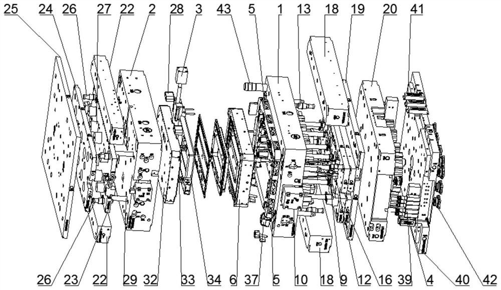
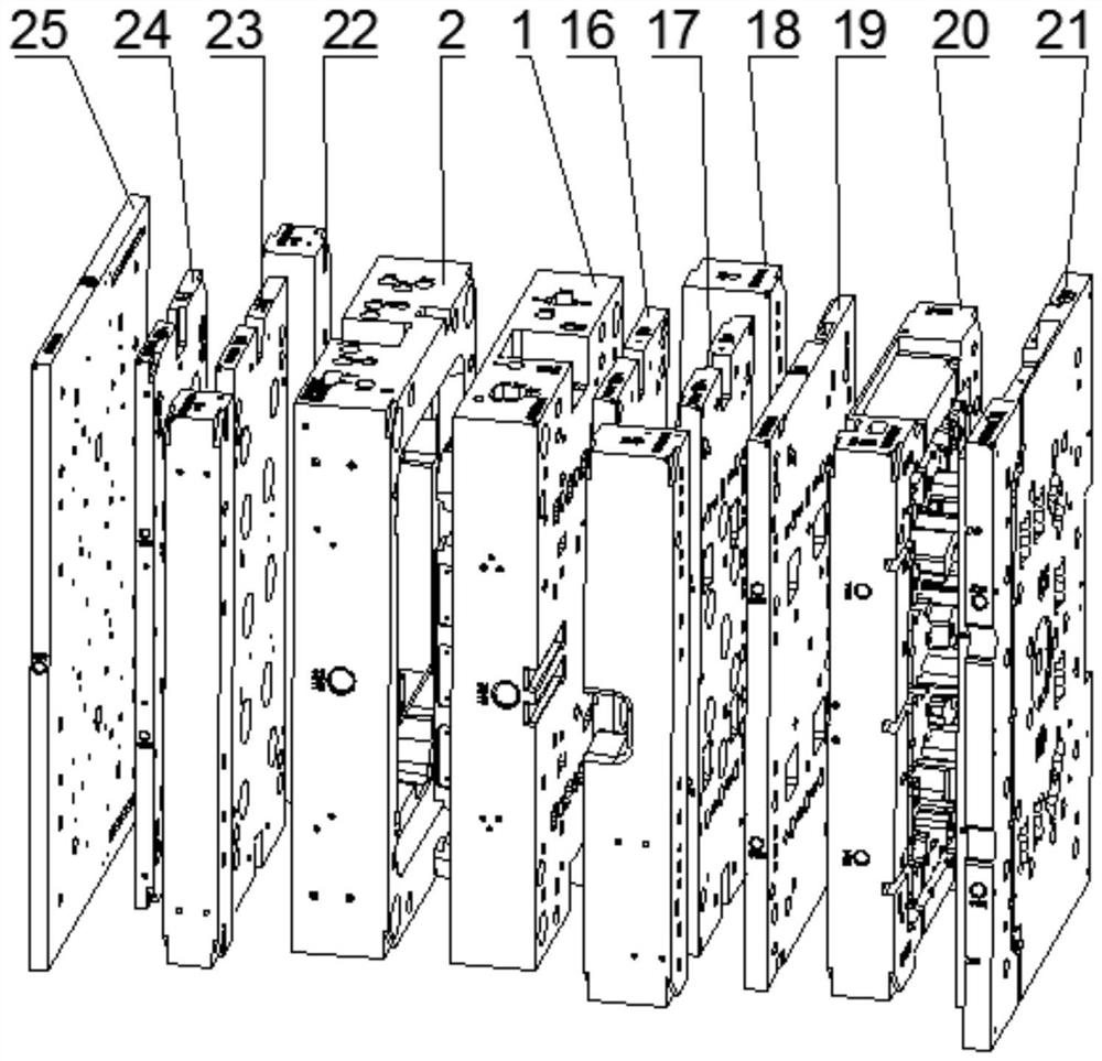
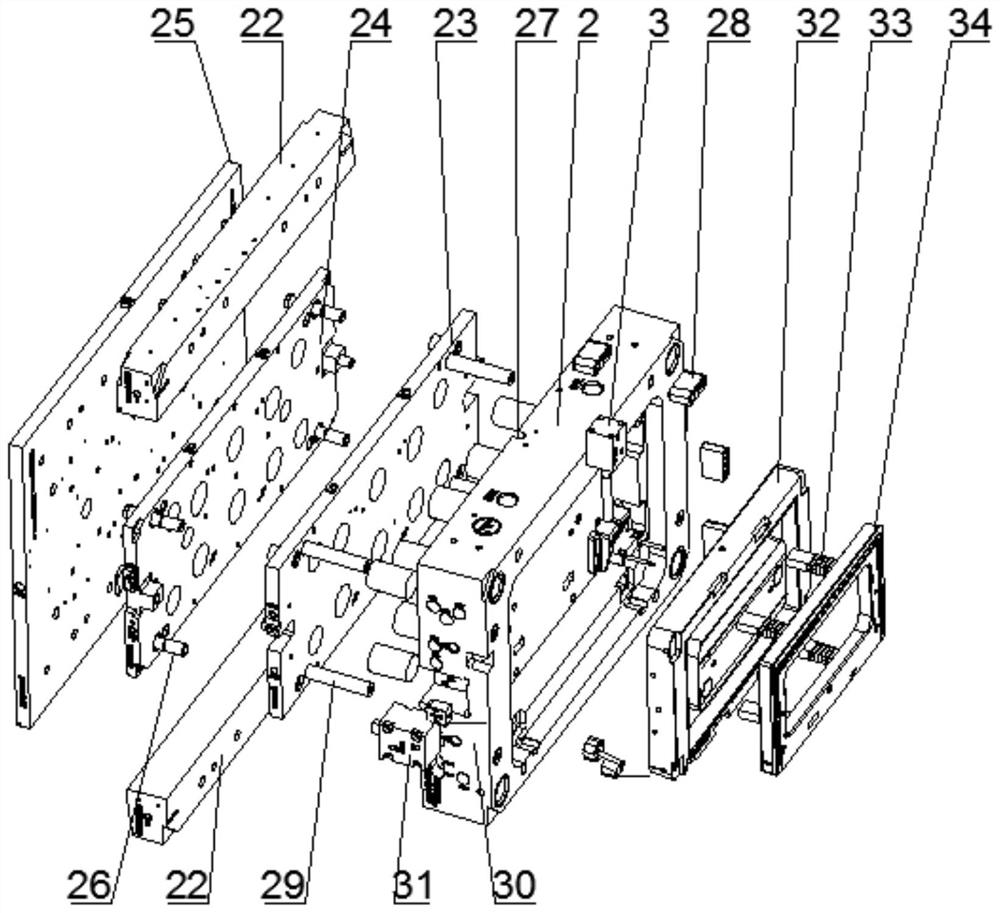
The invention relates to the technical field of acoustic-optical signal acquisition and conversion devices, in particular to an ultra-thin plastic coated iron mould with a mesh structure, and a usingmethod of the ultra-thin plastic coated iron mould. The ultra-thin plastic coated iron mould comprises a front mould plate, a rear mould plate, an oil cylinder and a sequential control junction box; the outer surface of one side of the front mould plate is fixedly connected with an abrasion-resistant block, one side of the front mould plate is connected with a front mould core, a front mould jacking block is mounted on one side of the front mould core, and one side of the front mould jacking block is fixedly connected with an oblique jacking part; and one side of a base plate is connected witha hot runner plate which is fixedly mounted on one side of a front mould fixing plate. During mould opening, a connected oblique column drives a mould position to be disengaged from a mesh structurepart, thus a product is smoothly demoulded and disengaged without pull damage, the problem of product damage is avoided, and the product yield is increased; on the other hand, the stability of a pushframe during production is improved, the problems such as inserting burning and clamping are not prone to occurring, and practicality is improved; and the overall practicality is high, and the use effect is better compared with a traditional mode.

Description

technical field [0001] The invention relates to the technical field of moulds, in particular to an ultra-thin plastic-coated iron mold with a mesh structure and a use method thereof. Background technique [0002] With the advancement of modern technology, displays are an indispensable product in modern life. The back shells of most displays in the market are usually made of plastic integral injection molding. The advantages of injection molding methods are fast production speed, High efficiency, automatic operation, various designs and colors, simple to complex shapes, large to small sizes, accurate product size, easy replacement of products, and the ability to form a variety of complex parts, and the existing In the manufacturing mold of the display case in the technology, the technology of the hot runner system used in the technology is not yet mature, which leads to excessive pressure and high temperature in the process of injection molding, which reduces the yield of the...

Claims


Application Information

Patent Timeline
Patent Type & Authority Patents(China)
IPC IPC(8): B29C45/26B29C45/27B29C45/33B29C45/40B29C45/00B29C45/76
CPCB29C45/0025B29C45/2602B29C45/27B29C45/2735B29C45/33B29C45/401B29C45/76B29C2045/0036B29C2045/4084B29C2945/76769B29C2945/76899
Inventor 黎成送
Owner 东莞市巨成模具有限公司
Learn More