A Radial Ultrasonic Vibration Lens Assisted Laser Processing Device

An ultrasonic vibration and auxiliary laser technology, applied in metal processing equipment, laser welding equipment, manufacturing tools, etc., can solve the problems of no laser focus measurement method, high requirements for laser overlap rate, and inability to guarantee processing quality, etc. The effect of overlapping ratio, improved surface quality and simple structure

Inactive Publication Date: 2020-11-24
NORTHEASTERN UNIV LIAONING
View PDF6 Cites 0 Cited by
  • Summary
  • Abstract
  • Description
  • Claims
  • Application Information

AI Technical Summary

Problems solved by technology

The focus position measurement methods for laser focusing mainly include inductive displacement sensor detection method, capacitive sensor detection method, printing method, inclined plate method, blue spark method, etc. The geometric error of the machine tool, the deformation of the machine tool under the load force, and the thermal deformation of the workpiece during the processing will cause the deviation of the laser focus position. Therefore, there is currently no accurate laser focus measurement method, resulting in the inability to guarantee high-precision processing quality.
After the laser beam is focused by the focusing lens, the focus radius is very small. In high-precision laser processing, the laser overlap rate is required to be high, which affects the processing efficiency. Workpiece Surface Quality

Method used


Image

  • A Radial Ultrasonic Vibration Lens Assisted Laser Processing Device
  • A Radial Ultrasonic Vibration Lens Assisted Laser Processing Device
  • A Radial Ultrasonic Vibration Lens Assisted Laser Processing Device

Examples


Embodiment Construction

[0021] The present invention will be further described in detail below in conjunction with the accompanying drawings and embodiments.

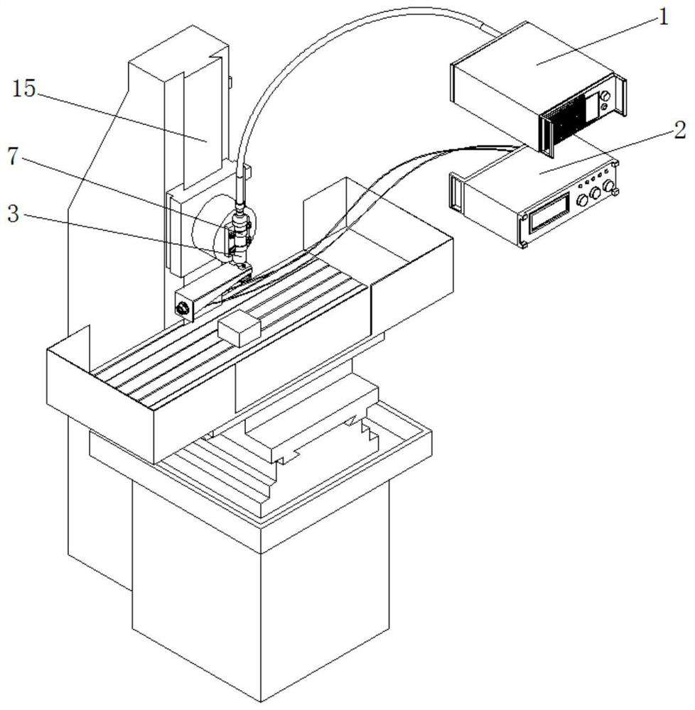
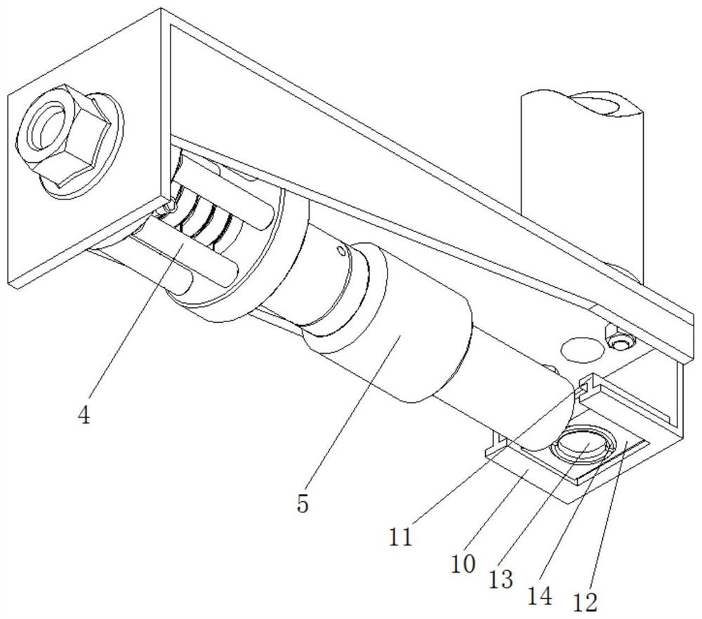
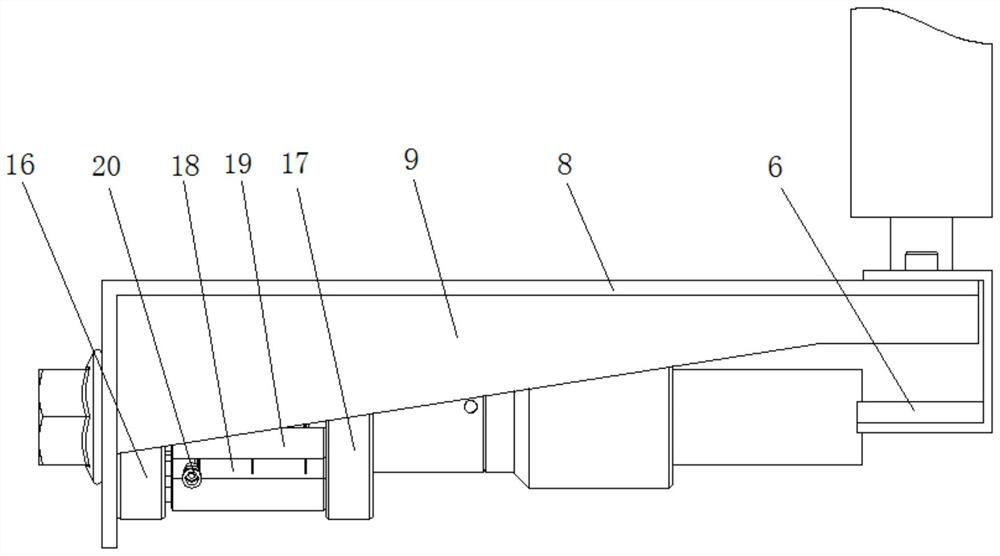
[0022] Such as Figure 1-4 As described above, a radial ultrasonic vibrating lens-assisted laser processing device includes a laser generator 1 and an ultrasonic generator 2, and the output end of the laser generator 1 is connected to one end of the collimating mirror 3 of the laser working head through an optical fiber terminal. The laser working head includes a collimating mirror 3, an ultrasonic transducer 4, a horn 5, a focusing lens mechanism 6 and a fixing frame. On the main shaft 15, the fixed frame includes a fixed frame connecting plate 8, and one end of the horizontal plate of the fixed frame connecting plate 8 is fixedly installed with the other end of the collimator mirror 3 through threads, and the fixed frame connecting plate 8 is vertically arranged with the collimating mirror 3, and fixed The vertical plate at the other end of...


PUM


Abstract

The invention provides a radial ultrasonic vibration lens assisted laser machining device, which comprises a laser generator and an ultrasonic generator. The output end of the laser generator is connected with one end of a collimating lens of a laser working head through an optical fiber terminal, the laser working head is composed of the collimating lens, an ultrasonic transducer, an amplitude changing rod, a focusing lens mechanism and a fixing frame, the laser working head is fixed to a machine tool spindle through the collimating lens, a clamp and an internal hexagon bolt, and the ultrasonic transducer is connected with the ultrasonic generator. According to the radial ultrasonic vibration lens assisted laser machining device, on the basis of an ordinary laser machining device, energydistribution at laser focusing focal points is changed by controlling an ultrasonic vibration lens, and thus the laser focusing focal points are changed from planar circle focal points into rounded rectangular three-dimensional focal points which are in direct proportion to the vibration amplitude of ultrasonic vibration and have certain radian; and energy distribution at the laser focusing focalpoints is changed under the effect of ultrasonic vibration, the defects on the surfaces of machined materials and the influence of other factors on the focal point positions are made up, and thus thesurface machining quality of workpieces is improved.

Description

technical field [0001] The invention belongs to the technical field of ultrasonic vibration composite laser processing, and in particular relates to a radial ultrasonic vibration lens-assisted laser processing device. Background technique [0002] With the rapid development of the manufacturing industry, the requirements for machining accuracy and machining efficiency of mechanical parts are getting higher and higher. In mechanical processing, the most basic and commonly used precision processing method is cutting processing, which plays an important role in the processing and production of various industries such as machinery, electronics, construction, etc. There are many factors that determine the accuracy and efficiency of cutting processing, such as Machine tools, cutting tools, workpieces, etc., among which cutting tools have the most obvious influence on them. The mechanical properties and processing performance of the tool material directly affect the service life o...

Claims


Application Information

Patent Timeline
Patent Type & Authority Patents(China)
IPC IPC(8): B23K26/00B23K26/04B23K26/70
CPCB23K26/00B23K26/04B23K26/70B23K26/702
Inventor 邹平吴昊康迪王文杰段经伟沈诚
Owner NORTHEASTERN UNIV LIAONING
Why Eureka
Try Eureka