
U-shaped steel composite beam member with self-contained shearing parts

A technology of shear parts and composite beams, which is applied in the direction of building components, building structures, floor slabs, etc., can solve the problems of large welding workload of shear connectors, less welding workload of shear parts, waste of steel on the upper flange, etc. , to achieve the effect of improving stability and fire prevention ability, reducing labor cost and good construction stability

Pending Publication Date: 2019-04-09
HANGXIAO STEEL STRUCTURE
View PDF0 Cites 1 Cited by
  • Summary
  • Abstract
  • Description
  • Claims
  • Application Information

AI Technical Summary

Problems solved by technology

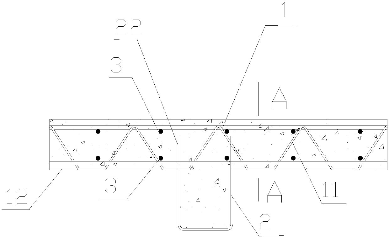
[0004] In order to solve the existing problems of poor construction stability, complex manufacture and installation, poor fire resistance, heavy welding workload of shear connectors, and waste of steel on the upper flange of existing composite beams, the present invention proposes a U-shaped steel composite beam components with self-contained shear parts, which save less welding workload, save unnecessary steel beam upper flanges, and improve the stability and fire resistance of composite steel beams in the construction stage.

Method used


Image

  • U-shaped steel composite beam member with self-contained shearing parts
  • U-shaped steel composite beam member with self-contained shearing parts
  • U-shaped steel composite beam member with self-contained shearing parts

Examples


Embodiment 1

[0035] Example 1 as figure 1 Shown: a U-shaped steel composite beam member with its own shear parts according to the present invention, including a reinforced truss floor deck 1, a steel beam 2, distributed steel bars 3, and a concrete layer 4, and the reinforced truss floor deck 1 It includes several steel bar trusses 11 and bottom film 12, the steel bar trusses 11 are arranged in parallel, and are fixed by a plurality of distributed steel bars 3 perpendicular to the steel bar trusses 11; the bottom film 12 is laid horizontally on the bottom of the steel bar trusses 11; The steel beam 2 is a U-shaped steel beam arranged horizontally, and the two edges of the steel beam 2 along the axial direction are provided with grooves 21 for clamping the steel truss, so that the edges of the steel beam are toothed edges 22, and adjacent The part between the two grooves is used as the shearing part of the steel beam; the steel beam truss 11 or the distributed steel bar 12 are inserted into...

Embodiment 2

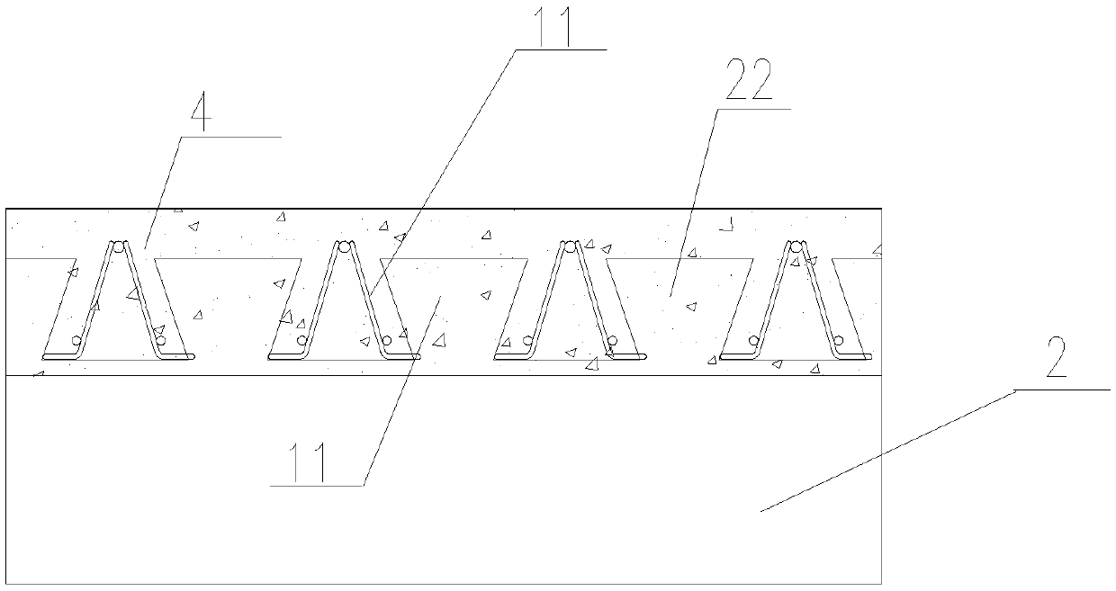
[0046] Example 2 as figure 2 As shown, the difference between this embodiment and Embodiment 1 is that: the steel beams and steel trusses are parallel to the bottom membrane, and the steel beams and steel trusses are parallel; other structures are the same as in Embodiment 1.

Embodiment 3

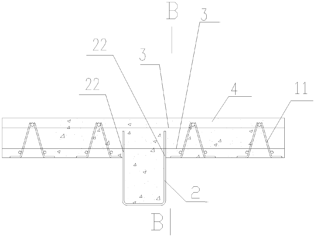
[0047] Embodiment 3 The difference between this embodiment and Embodiment 1 is that the steel girder 2 is a welded U-shaped steel girder, the steel girder 2 includes a bottom plate and two side plates, and the two opposite edges of the bottom plate along the axial direction are respectively The side plate is welded, and the three form a U-shaped steel beam, and the top edge of the side plate is provided with a trapezoidal groove.

[0048] Both the steel beam and the steel truss are parallel to the bottom membrane, and the steel beam is perpendicular to the steel truss.


PUM


Abstract

The invention discloses a U-shaped steel composite beam member with self-contained shearing parts. The U-shaped steel composite beam member comprises a steel bar truss floor slab, a steel beam, distributing steel bars and a concrete layer, wherein the steel bar truss floor slab comprises a plurality of steel bar trusses and a bottom film; the steel bar trusses are arranged in parallel and are fixed by a plurality of the distributing steel bars perpendicular to the steel bar trusses; the bottom film is horizontally laid at the bottoms of the steel bar trusses; the steel beam is a horizontally arranged U-shaped steel beam; grooves for clamping the steel bar trusses are formed in two edges of the steel beam in the axial direction; the steel bar trusses or the distributing steel bars are clamped in the grooves of the steel beam; the steel beam serves as a support of the steel bar truss floor slab; and the concrete layer is poured into gaps among the steel bar trusses, the distributing steel bars and the steel beam, located on the surface of the bottom film, of the steel bar truss floor slab to form a floor. The U-shaped steel composite beam member has the benefits that a U-shaped crosssection improves the stability of a composite beam in the construction stage, avoids the addition of temporary supports during the construction, increases the shear resistance of the composite beam and improves the stability and fire prevention of a U-shaped steel beam web.

Description

technical field [0001] The invention relates to a U-shaped steel composite beam component with its own shearing parts. Background technique [0002] The steel-concrete composite beam refers to the load-bearing member that connects the steel beam and the concrete slab as a whole through shear connectors. The concrete in the composite beam section is mainly under compression, and the steel beam is under tension, which gives full play to the material properties and has a high bearing capacity. [0003] Most of the existing steel and concrete composite beams realize the combined effect of the steel beam and the concrete floor slab by welding the shear connectors on the upper flange of the H-shaped steel beam. The shear connectors usually use studs, and channel steel, bending bars, etc. can also be used. The connection between the shear connectors and the steel beam requires a lot of welding work and costs; at the same time, the upper wing of the H-shaped steel beam participates...

Claims


Application Information

Patent Timeline
IPC IPC(8): E04B5/28
CPCE04B5/28
Inventor 刘晓光郭立湘张彬单银木徐韶锋易建文束炜陈鹏骆贵波谢优胜高小强方励陈羽陈芳童卫华殳非闲李庆刚刘重阳张红梅江志武
Owner HANGXIAO STEEL STRUCTURE
Learn More