


Quick Research
Generate reliable direction feasibility study reports for your R&D in just a few steps.

Technical Q&A
Discover and master advanced knowledge NOW. Basics, ideas, possibilities, all at once.

Find Solutions
As an expert in R&D theories, this can generate solutions to your technical problems instantly.

Evaluate Feasibility
Analyze your overall solution with one click, know your potential R&D risks in advance.

Monitor Landscape
Get weekly tech updates, stay abreast of the latest tech innovations and key insights.
Shielded connector and its connection method
A connector and shielding technology, applied in the direction of connection, two-part connection device, and components of the connection device, etc., can solve the problems of impedance mismatch and change, and achieve easy impedance matching, improved shielding characteristics, and simple structure. Effect
- Summary
- Abstract
- Description
- Claims
- Application Information
AI Technical Summary
Problems solved by technology
Method used
Image

Examples
Embodiment 1
[0047] Hereinafter, Embodiment 1 of the present invention will be described based on the drawings.
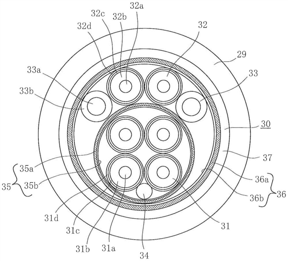
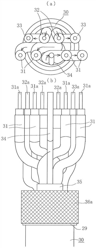
[0048] figure 2 The 8-core composite shielded electric wire 30 used in the shielded connector and its connection method of the present invention is shown. The composite shielded electric wire 30 in this example has 6 shielded single-core wires, of which 4 shielded single-core wires 31 are high-speed wires used in differential signal transmission and the like, and the two shielded single-core wires 32 include medium-speed wires. The composite shielded electric wire 30 also has two power lines 33 and one drain wire 34.
[0049] The conductor 31a at the center of the four high-speed wires 31 is covered by an insulator 31b, and the outer periphery is covered by a single-core wire shielding portion including a horizontally wound shielding portion 31c and an aluminum tape 31d. Similarly, the two medium-speed wires 32 The conductor 32a in the center is covered by an insulator 32b, and th...
Embodiment 2
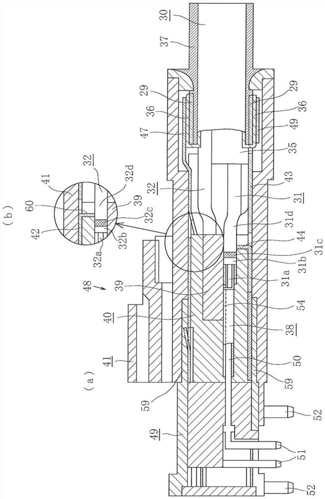
[0066] Although in the above-mentioned embodiment, the cut-and-raised piece 44 is provided for the high-speed wire 31 for differential signal transmission to achieve impedance matching over the entire area of the exposed portion, the same configuration may be adopted for the medium-speed wire 32. Thus, as figure 1 As shown in (b), a part of the shielding shell 42 is grooved downward to form a cut-and-raised piece 60 of the shielding member of the connector. The single core wire shielding portion of the aluminum tape 32d can thereby achieve impedance matching in the entire area of the exposed portion of the medium-speed wire 32, and can enhance the shielding effect.
[0067] In the above embodiment, the connection between the single-core wire shielding portion of the high-speed wire 31 and the cut-and-raised piece 44 and / or the connection between the single-core wire shielding portion of the medium-speed wire 32 and the cut-and-raised piece 60 has excellent workability, There...
PUM
 Abstract
Description
Claims
Application Information
 - R&D Engineer
- R&D Manager
- IP Professional
- Industry Leading Data Capabilities
- Powerful AI technology
- Patent DNA Extraction
Browse by: Latest US Patents, China's latest patents, Technical Efficacy Thesaurus, Application Domain, Technology Topic, Popular Technical Reports.
© 2024 PatSnap. All rights reserved.Legal|Privacy policy|Modern Slavery Act Transparency Statement|Sitemap|About US| Contact US: help@patsnap.com