
Scanning device and transition method thereof

A scanning device and extending direction technology, applied in the field of scanning and inspection, can solve the problems of long time consumption, large manpower input, difficult transportation, etc., and achieve the effects of improving the convenience of use, shortening the time consumption, and shortening the disassembly time.

Pending Publication Date: 2019-03-26
NUCTECH CO LTD +2
View PDF6 Cites 8 Cited by
  • Summary
  • Abstract
  • Description
  • Claims
  • Application Information

AI Technical Summary

Problems solved by technology

Especially for some relatively large scanning devices, due to their large size and difficult transfer, they may not meet the transportation height requirements of the road during transportation, and due to the limitation of the size of the transportation equipment, it is generally necessary to place each part of the scanning device during transportation. Parts are dismantled, such as boom, cabin, detector, ray source, etc., and then reinstalled and debugged at the job site
Moreover, it is necessary to rebuild the protective wall and carry out the civil work of the protective wall on site, which takes a long time and requires a large amount of manpower input.
[0004] Therefore, the operation of the scanning device is cumbersome when it needs to be transferred, and it is not easy to ensure the detection accuracy of the scanning device due to the influence of repeated installation.

Method used


Image

  • Scanning device and transition method thereof
  • Scanning device and transition method thereof
  • Scanning device and transition method thereof

Examples


Embodiment Construction

[0040] The present invention will be described in detail below. In the following paragraphs, different aspects of the embodiments are defined in more detail. Aspects so defined may be combined with any other aspect or aspects unless specifically stated otherwise. In particular, any feature considered to be preferred or advantageous may be combined with one or more other features which are considered to be preferred or advantageous.

[0041] Terms such as "first" and "second" appearing in the present invention are only for convenience of description, to distinguish different components with the same name, and do not indicate a sequence or a primary and secondary relationship.

[0042] In the description of the present invention, orientations or positional relationships indicated by "upper", "lower", "top", "bottom", "front", "rear", "inner" and "outer" are used based on the attached The orientation or positional relationship shown in the figure is only for the convenience of ...


PUM


Abstract

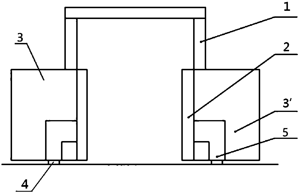
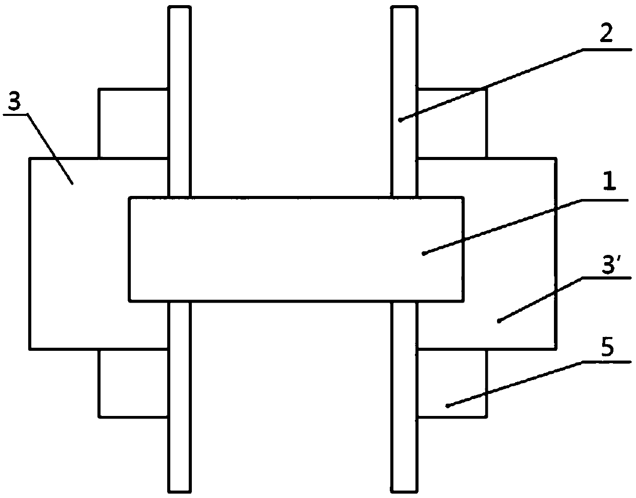
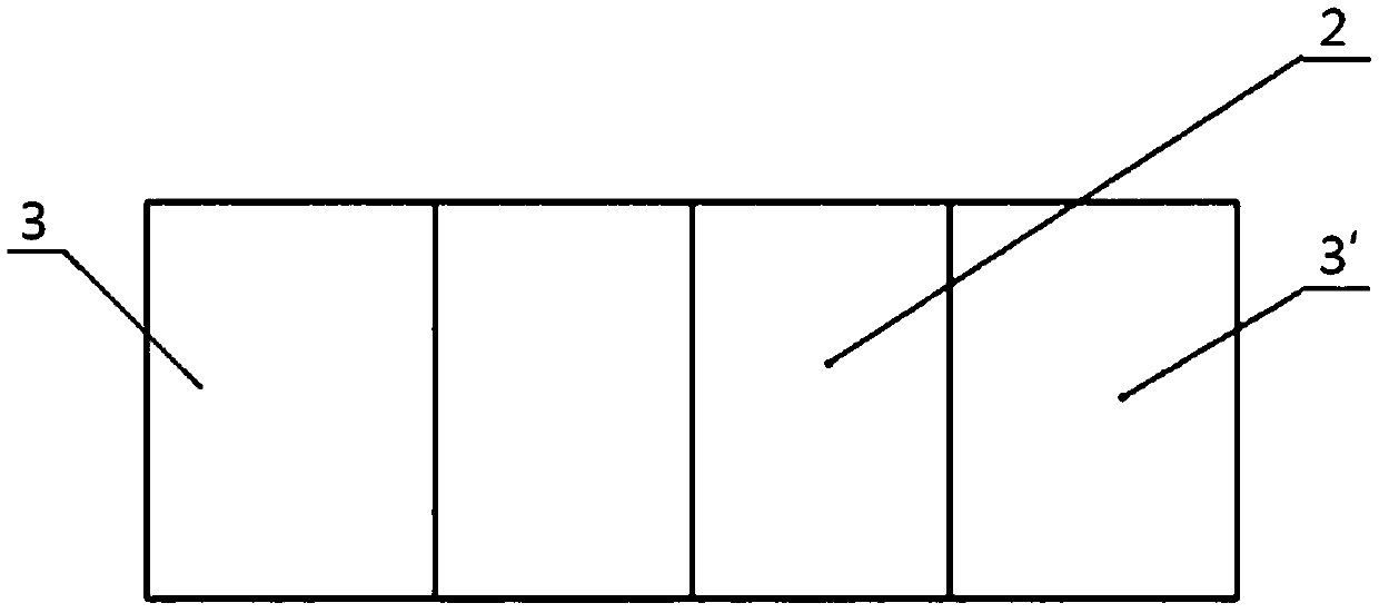
The invention relates to a scanning device and a transition method thereof. The scanning device includes an arm stand (1) which is provided with multiple detectors and is used for forming an inspection channel, a first cabin (3) which is internally provided with a ray source and is connected with the arm stand (1), a protection wall (2) which is connected with the first cabin (3) or the arm stand(1) and is used for performing ray protection for a to-be-protected object, and a tire used for making the scanning device to move relative to the ground, wherein the arm stand (1), the first cabin (3) and the protection wall (2) are set to transport together in a connection state. The scanning device is advantaged in that when the scanning device needs transition, the link of re-mounting at the inspection site can be omitted, the dismounting time can be shortened, transition efficiency is improved, protection wall re-establishment and protection wall civil engineering works in the inspectionsite can be avoided, and the scanning device can be quickly put into work after being transported to the inspection site.

Description

technical field [0001] The invention relates to the technical field of scanning inspection, in particular to a scanning device and a transition method thereof. Background technique [0002] Scanning devices are devices installed in ports, customs and civil aviation airports to inspect containers or moving vehicles. The scanning device uses the principle of radiation imaging to scan the object to be inspected passing through it to obtain a perspective image of the object to be inspected, thereby realizing scanning inspection. [0003] According to the requirements of use, the scanning device sometimes needs to be transported to different places to perform inspection tasks. Especially for some relatively large scanning devices, due to their large volume, it is difficult to transfer, and may not meet the transportation height requirements of the road during transportation, and due to the limitation of the size of the transportation equipment, it is generally necessary to place...

Claims


Application Information

Patent Timeline
Patent Type & Authority Applications(China)
IPC IPC(8): G01V5/00
CPCG01V5/22
Inventor 宋全伟樊旭平史俊平何远孟辉宗春光胡煜孙尚民曹金国
Owner NUCTECH CO LTD
Learn More