
On-site horizontal splicing method of steel tube arch

A steel pipe arch and on-site technology, which is applied in the erection/assembly of bridges, bridge materials, bridges, etc., can solve the problems of high-altitude alignment risks, inaccurate alignment, and difficult installation, achieving fast adjustment speed and less space occupation , high safety effect

Active Publication Date: 2019-03-22
中铁一局集团厦门建设工程有限公司 +1
View PDF2 Cites 5 Cited by
  • Summary
  • Abstract
  • Description
  • Claims
  • Application Information

AI Technical Summary

Problems solved by technology

[0002] Now it is necessary to carry out on-site horizontal jointing of the 220m-span steel pipe arch. Under the existing technical conditions, the linear control accuracy of the horizontal jointing of the arch curve is poor, and the welding deformation is large. Cranes are often used for auxiliary construction. The construction efficiency is low and the safety is low. high risk
On-site steel components are complex and diverse, making it difficult to manage
Manufactured steel arch ribs have not been pre-cambered and pre-assembled, resulting in a large difference between the control points of the arch ribs and the manufacturing control points during the on-site installation process, and the precise alignment cannot be achieved
In addition, when the butt welding technology is used between the arch rib segments, the installation is difficult and the risk of high-altitude alignment is high

Method used


Image

  • On-site horizontal splicing method of steel tube arch
  • On-site horizontal splicing method of steel tube arch
  • On-site horizontal splicing method of steel tube arch

Examples


Embodiment Construction

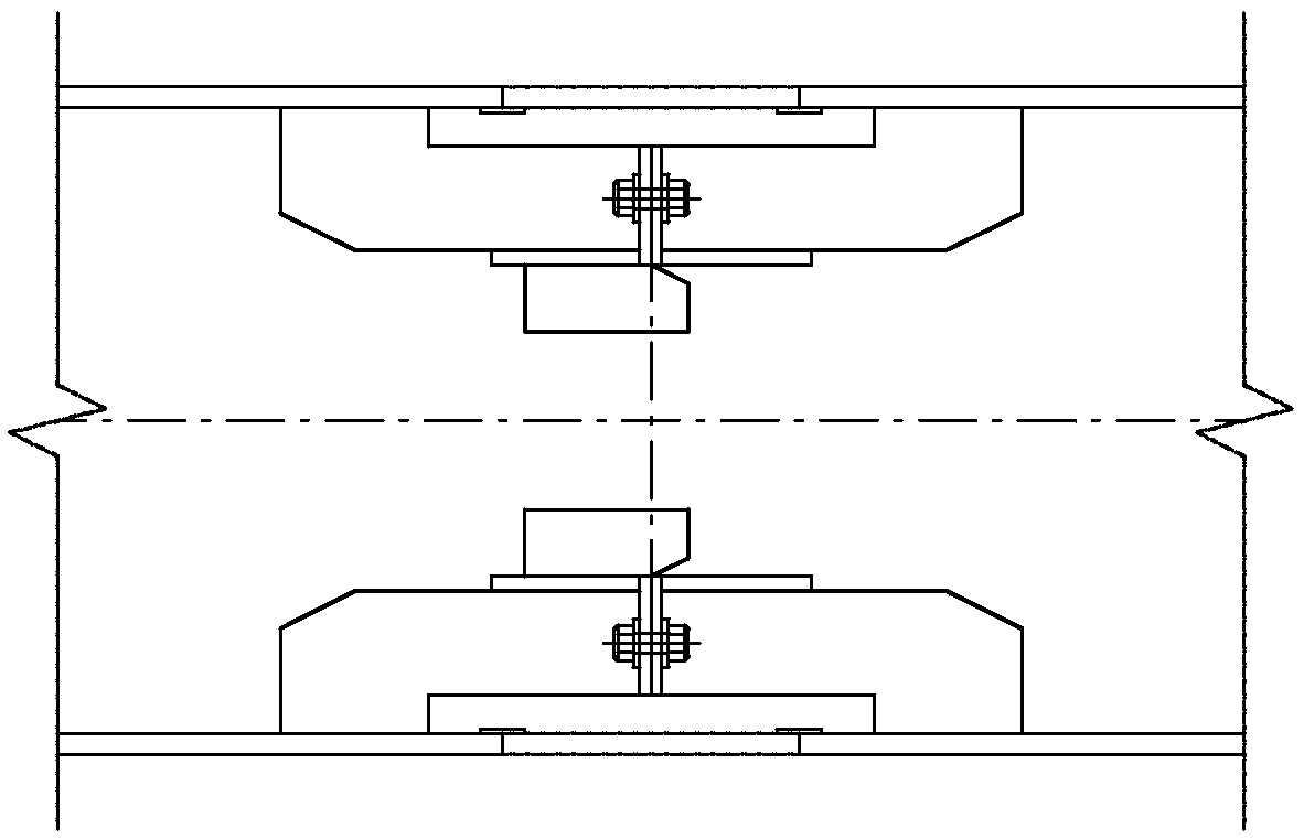
[0033] Please check Figure 1 to Figure 3 , a method for on-site horizontal assembly of steel pipe arches. In order to facilitate the management of steel components and consider the requirements of the construction site, component unit processing and group management are carried out in separate factories. The component units are processed and manufactured in the rear processing plant. Transport to the site for horizontal assembly and welding.

[0034] The component units transported to the site shall be checked and accepted item by item, compared, stacked and taken as required, and installed in strict accordance with the design.

[0035] The chord unit of the arch rib segment is connected by straight pipe, which is made by folding instead of bending. The length of the straight pipe is 1-3.6m. After passing the non-destructive test, it is rounded to ensure that the sagittal roundness of the pipe joint meets the requirements of the specification. The longitudinal butt welds bet...


PUM


Abstract

The invention discloses an on-site horizontal splicing method of a steel tube arch, which adopts horizontal splicing in the form of '3+1' to meet the requirements of the alignment and can be processedand manufactured normally. The method adopts a mode of drawing a ground sample and then hanging a vertical line to lead the wire to be centered and aligned, is convenient and practical, and ensures horizontal splicing precision and linear smoothness. An inner flange is adopted to connect the two arch rib sections, the connection precision is high, the adjusting speed is high when a steel beam iserected in the later period, and the safety of the inner flange is high. The arrangement of a pre-arch degree is considered during horizontal splicing, so that the problem that the linear change caused by the pre-arch degree in the erection process cannot accurately align an inner flange bolt is avoided, and unnecessary trouble is caused. The on-site horizontal splicing method of the steel tube arch adopts the mode of steel component processing and on-site assembly separation, and is convenient for management and error prevention by batch entry and batch acceptance. The middle part is welded first, and then the two sides are welded to prevent stress concentration. After the arch rib is welded, welding the inner flange and the arch rib which are connected by bolts in advance; the deformation caused by the shrinkage of a welding seam cannot be prevented so that the inner flange cannot be accurately aligned.

Description

technical field [0001] The invention relates to a method for on-site lying assembly of a steel pipe arch. Background technique [0002] Now it is necessary to carry out on-site horizontal joint construction of the 220m span steel pipe arch. Under the existing technical conditions, the horizontal joint linear control accuracy of the arch curve is poor, and the welding deformation is large. Cranes are often used for auxiliary construction. The construction efficiency is low and the safety is low. Risky. On-site steel components are complex and diverse, and difficult to manage. The manufactured steel arch ribs have not been pre-cambered and pre-assembled, resulting in a large difference between the control points of the arch ribs and the manufacturing control points during the on-site installation process, and the precise alignment cannot be achieved. Moreover, when the butt welding technology is used between the arch rib segments, the installation is difficult and the risk o...

Claims


Application Information

Patent Timeline
IPC IPC(8): E01D21/10
CPCE01D21/10E01D2101/26
Inventor 白利勇马欣尚武孝陈慧党宏斌赵绪勇苏本林骆国建赵恒魏莹飞
Owner 中铁一局集团厦门建设工程有限公司
Learn More