Self-sensing driver based on magnetostrictive material
A technology of magnetostrictive materials and magnetostrictive rods, applied in the direction of piezoelectric effect/electrostrictive or magnetostrictive motors, generators/motors, electrical components, etc., can solve the single drive or sensing function, structure Not compact, no integration and other problems, to achieve the effect of improving driving accuracy and sensing efficiency, improving detection sensitivity, and improving compactness
- Summary
- Abstract
- Description
- Claims
- Application Information
AI Technical Summary
Problems solved by technology
Method used
Image
Examples
Embodiment 1
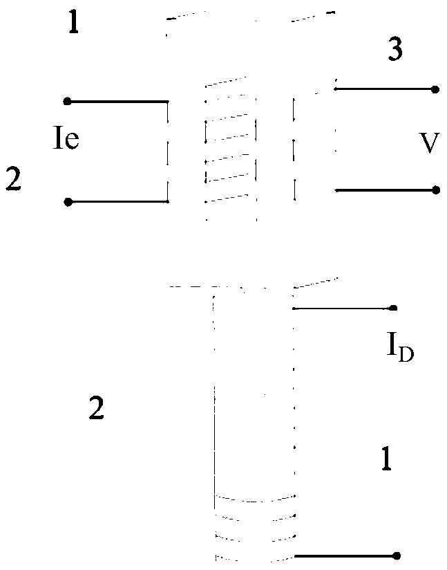
[0056] Such as figure 1 As shown, the driving part is mainly composed of a driving body wound with a driving coil, wherein the driving body is mainly composed of a magnetostrictive rod; the sensing body of the sensing part is mainly made of a rectangular frame-shaped magnetostrictive material, Coils are wound on the left and right sides, one side is the excitation coil, and the other side is the induction coil. The end where the sensing body collides with the driving body is provided with a semicircular protrusion. The function of the semicircle protrusion is to ensure the driving The force exerted by the body on the sensing body is applied along the axial direction to avoid bending moment.
[0057] Input the exciting high-frequency small current Ie to the exciting coil, and the induction coil outputs the induced voltage V under the action of exciting high-frequency small current Ie 1 ; Input the driving current I to the driving coil D , the driving body elongates and hits t...
Embodiment 2
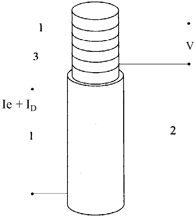
[0059] Such as figure 2 As shown, the driving part is mainly composed of a driving body wound with a driving coil, wherein the driving body is mainly composed of a magnetostrictive cylinder; the sensing body of the sensing part is mainly composed of a magnetostrictive rod, and the sensing body It is built in the cylinder of the driving body, wherein the induction coil is wound on the sensing body, and the driving coil of the driving part also constitutes the excitation coil of the sensing part.
[0060] Input the drive current I to the drive coil D The superimposed excitation high-frequency small current Ie, the induction coil outputs the induced voltage V under the action of the excitation current 1 , the driver is driving the current I D Under the action of elongation, it hits the sensing body, and the sensing body is subjected to stress to produce the Villari effect, and the magnetic field of the sensing body changes, so that the induced voltage output by the induction c...
Embodiment 3
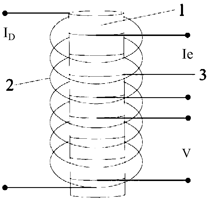
[0063] Such as image 3 As shown, the driving body of the driving part and the sensing body of the sensing part include the same magnetostrictive rod, coils arranged radially inside and outside are wound on the magnetostrictive rod, the driving coil is wound on the outside, and the excitation coil is wound on one end of the inside. coil, and the other end of the inner side is wound with an induction coil.
[0064] Input the excitation high-frequency small current Ie to the induction excitation coil, and the induction coil outputs the induction voltage V under the action of the excitation current 1 , input the driving current I to the driving coil D , the magnetostrictive rod at the driving current I D Under the action of elongation, the Villari effect is generated after elongation, and the magnetic field changes, so that the induced voltage output by the induction coil becomes V 2 , by measuring V(δ)=V 1 -V 2 The displacement and force of the driving part are detected.
PUM
 Abstract
Description
Claims
Application Information
 - R&D
- Intellectual Property
- Life Sciences
- Materials
- Tech Scout
- Unparalleled Data Quality
- Higher Quality Content
- 60% Fewer Hallucinations
Browse by: Latest US Patents, China's latest patents, Technical Efficacy Thesaurus, Application Domain, Technology Topic, Popular Technical Reports.
© 2025 PatSnap. All rights reserved.Legal|Privacy policy|Modern Slavery Act Transparency Statement|Sitemap|About US| Contact US: help@patsnap.com


