
Diffraction wave imaging method and device and electronic equipment

A diffracted wave and diffraction technology, applied in the field of seismic exploration, can solve the problems of poor accuracy of imaging results, difficulty in completely removing multiple reflections and other interference waves, and low imaging accuracy of diffracted waves, so as to improve imaging accuracy and improve Effects of Accuracy and Focusability

Active Publication Date: 2019-03-19
CHINA UNIV OF MINING & TECH (BEIJING)
View PDF6 Cites 2 Cited by
  • Summary
  • Abstract
  • Description
  • Claims
  • Application Information

AI Technical Summary

Problems solved by technology

[0002] During the mining of mineral resources, disasters such as water inrush, gas outburst, and roof collapse seriously affect mining efficiency and personnel safety. Diffraction wave exploration technology can improve the prediction accuracy of geological anomalies such as faults and collapse columns, which is an effective way to avoid these geological problems. An important means of disasters, but the existing diffraction wave imaging method is difficult to completely remove multiple reflections and other interference waves, the imaging accuracy of diffraction wave is not high, and the accuracy of imaging results is poor

Method used


Image

  • Diffraction wave imaging method and device and electronic equipment
  • Diffraction wave imaging method and device and electronic equipment
  • Diffraction wave imaging method and device and electronic equipment

Examples


Embodiment Construction

[0023] In order to make the purpose, technical solutions and advantages of the embodiments of the present invention clearer, the technical solutions of the present invention will be clearly and completely described below in conjunction with the accompanying drawings. Obviously, the described embodiments are part of the embodiments of the present invention, not all of them. the embodiment. Based on the embodiments of the present invention, all other embodiments obtained by persons of ordinary skill in the art without making creative efforts belong to the protection scope of the present invention.

[0024] At present, the plane wave deconstruction filter can be used to suppress the reflected wave and enhance the diffracted wave. However, this method relies heavily on the prediction of the local inclination value of the reflected wave, and the separated diffracted wave contains interference such as noise, which affects Based on the imaging results of diffracted waves, a diffracte...


PUM


Abstract

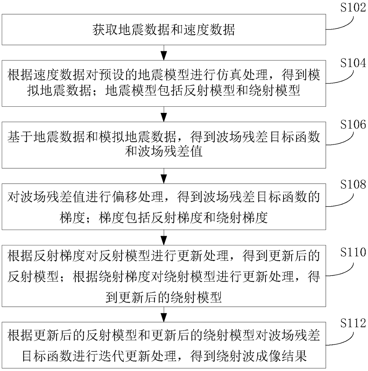
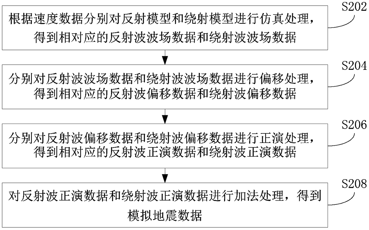
The invention provides a diffraction wave imaging method and device and electronic equipment, wherein the method comprises the following steps: acquiring seismic data and velocity data; carrying out simulation processing on a preset seismic model according to the speed data to obtain simulated seismic data, wherein the seismic model comprises a reflection model and a diffraction model; obtaining awave field residual error objective function and a wave field residual error value based on the seismic data and the simulated seismic data; performing migration processing on the wave field residualerror value to obtain a gradient of a wave field residual error objective function, wherein the gradient comprises a reflection gradient and a diffraction gradient; updating the reflection model andthe diffraction model respectively according to the reflection gradient and the diffraction gradient to obtain an updated reflection model and an updated diffraction model; performing iterative updating processing on the wave field residual error objective function according to the updated reflection model and the updated diffraction model to obtain a diffraction wave imaging result. According tothe diffraction wave imaging method, the migration method is utilized, and the least square idea is combined, thereby effectively improving the diffraction wave imaging precision, and improving the accuracy and the focusing performance of an imaging result.

Description

technical field [0001] The invention relates to the technical field of seismic exploration, in particular to a diffraction wave imaging method, device and electronic equipment. Background technique [0002] During the mining of mineral resources, disasters such as water inrush, gas outburst, and roof collapse seriously affect mining efficiency and personnel safety. Diffraction wave exploration technology can improve the prediction accuracy of geological anomalies such as faults and collapse columns, which is an effective way to avoid these geological problems. However, the existing diffraction wave imaging method is difficult to completely remove multiple reflections and other interference waves, and the imaging accuracy of diffraction wave is not high, and the accuracy of imaging results is poor. Contents of the invention [0003] In view of this, the object of the present invention is to provide a diffracted wave imaging method, device and electronic equipment, so as to ...

Claims


Application Information

Patent Timeline
Patent Type & Authority Applications(China)
IPC IPC(8): G01V1/28
CPCG01V1/282
Inventor 李闯建彭苏萍赵惊涛崔晓芹
Owner CHINA UNIV OF MINING & TECH (BEIJING)
Learn More