D-shaped micro-column mirror rotary SPR (surface plasmon resonance) sensing chip
A sensor chip and mirror rotation technology, which is applied to measuring devices, instruments, and material analysis through optical means, can solve problems such as high cost, large instrument volume, and inconvenient replacement of sensing structures, and achieve low cost and real The effect of high-resolution modulation
- Summary
- Abstract
- Description
- Claims
- Application Information
AI Technical Summary
Problems solved by technology
Method used
Image
Examples
Embodiment 1
[0041] Embodiment 1: Preparation of D-shaped microcylindrical lens rotating SPR sensor chip
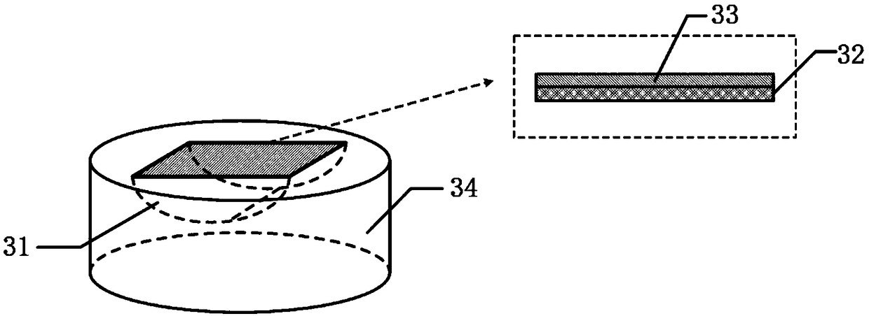
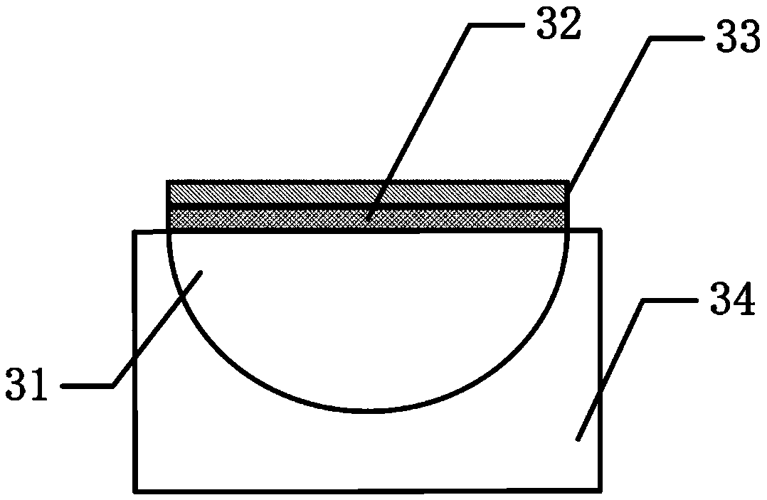
[0042] Such as figure 2 and image 3 Shown, the preparation method of a kind of D-shaped microcylindrical mirror rotating SPR sensor chip is as follows:
[0043] First prepare the D-shaped micro-cylindrical lens optical substrate: heat-melt the preformed rod to make a D-shaped quartz or glass micro-rod, then use polishing technology to polish the side of the D-shaped quartz or glass micro-rod, and then make the D-shaped micro-rod Quartz or glass microrods are cut into appropriate lengths to obtain D-shaped microcylindrical lens optical substrates.
[0044] Then prepare a nano-metal film on the end face of the D-shaped micro-cylindrical optical substrate, taking the gold film as an example: a gold film with a thickness of about 50 nm is plated on the end face of the D-shaped micro-cylindrical optical substrate by sputtering. Of course, the gold film can also be prepared according t...
Embodiment 2
[0047] Embodiment 2: Simulation test of D-shaped microcylindrical lens rotating SPR sensor chip
[0048] Figure 6 It is a graph of the relationship between the horizontal rotation angle of the rotating platform and the incident angle of excitation light obtained through simulation calculation. In this simulation, the initial incident angle of the excitation light wave on the surface of the gold film is set to 72°, and as the horizontal direction of the rotating platform rotates every 0.01°, the incident angle changes accordingly. According to the simulation test, the rotation angle of the rotating platform has a good linearity in the change of the excitation angle in the range of 30°-60°, and the change of the resonance angle can reach 0.001° for every 0.01° rotation of the rotating platform. Therefore, the resonance angle measurement accuracy of the indirect angle modulation method is 10 times higher than that of the traditional direct angle modulation method.
[0049] F...
Embodiment 3
[0051] Embodiment 3: Application test of D-shaped microcylindrical lens rotating SPR sensor chip
[0052] The prepared D-shaped microcylindrical rotating SPR sensor chip can be directly connected to the sensor system for testing the liquid to be tested. Such as figure 1 As shown, the He-Ne laser 1 with a central wavelength of 632.8nm generates an optical signal, which is input to the polarization controller 2 by a single-mode fiber to control the output to become P-polarized light, and the P-polarized light is incident on the D-shaped micro-cylindrical rotating SPR The sensor chip 3 adjusts the incident angle of the incident light so that the light coincides with the radius of the D-shaped micro-lens optical substrate 31 . As the rotary platform 4 on which the D-shaped microcylindrical lens rotating SPR sensor chip 3 is placed rotates horizontally forward or horizontally in reverse, the incident angle of the incident light wave changes accordingly. When the incident angle rea...
PUM
| Property | Measurement | Unit |
|---|---|---|
| thickness | aaaaa | aaaaa |
| thickness | aaaaa | aaaaa |
| thickness | aaaaa | aaaaa |
Abstract
Description
Claims
Application Information
 - R&D
- Intellectual Property
- Life Sciences
- Materials
- Tech Scout
- Unparalleled Data Quality
- Higher Quality Content
- 60% Fewer Hallucinations
Browse by: Latest US Patents, China's latest patents, Technical Efficacy Thesaurus, Application Domain, Technology Topic, Popular Technical Reports.
© 2025 PatSnap. All rights reserved.Legal|Privacy policy|Modern Slavery Act Transparency Statement|Sitemap|About US| Contact US: help@patsnap.com


