
Air flotation main shaft bearing compensation device and method

An air-floating spindle and compensation device technology, which is applied to bearings, hydrostatic bearings, shafts and bearings, etc., can solve the problems of difficult to guarantee machining accuracy, increased spindle rotation error, and wear and tear of the air-floated spindle, and achieve real-time compensation. , High loading accuracy, and the effect of improving accuracy

Pending Publication Date: 2019-03-19
HANGZHOU DIANZI UNIV
View PDF0 Cites 8 Cited by
  • Summary
  • Abstract
  • Description
  • Claims
  • Application Information

AI Technical Summary

Problems solved by technology

During the working process of the air bearing spindle, due to the feed of the cutter head, the cutting force and the high-speed rotation of the spindle, the rotation error of the spindle is likely to increase, and the machining accuracy is difficult to guarantee. When the bearing capacity is too large, the air bearing spindle may even wear out and fail.
[0003] At present, for the rotation error caused by vibration or tool feed during the working process of the air bearing, the weight type or spring type is directly used for load compensation. The connection between the loader and the bearing in this compensation method is generally a rigid connection. , real-time detection and bearing compensation cannot be realized, and the loading force cannot guarantee the accuracy

Method used


Image

  • Air flotation main shaft bearing compensation device and method
  • Air flotation main shaft bearing compensation device and method
  • Air flotation main shaft bearing compensation device and method

Examples


Embodiment Construction

[0026] The present invention will be further described below in conjunction with accompanying drawing.

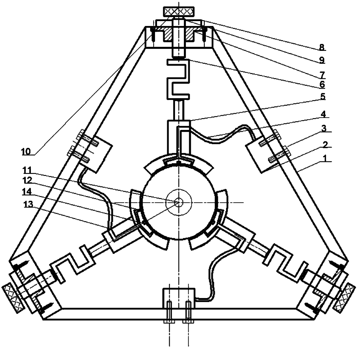
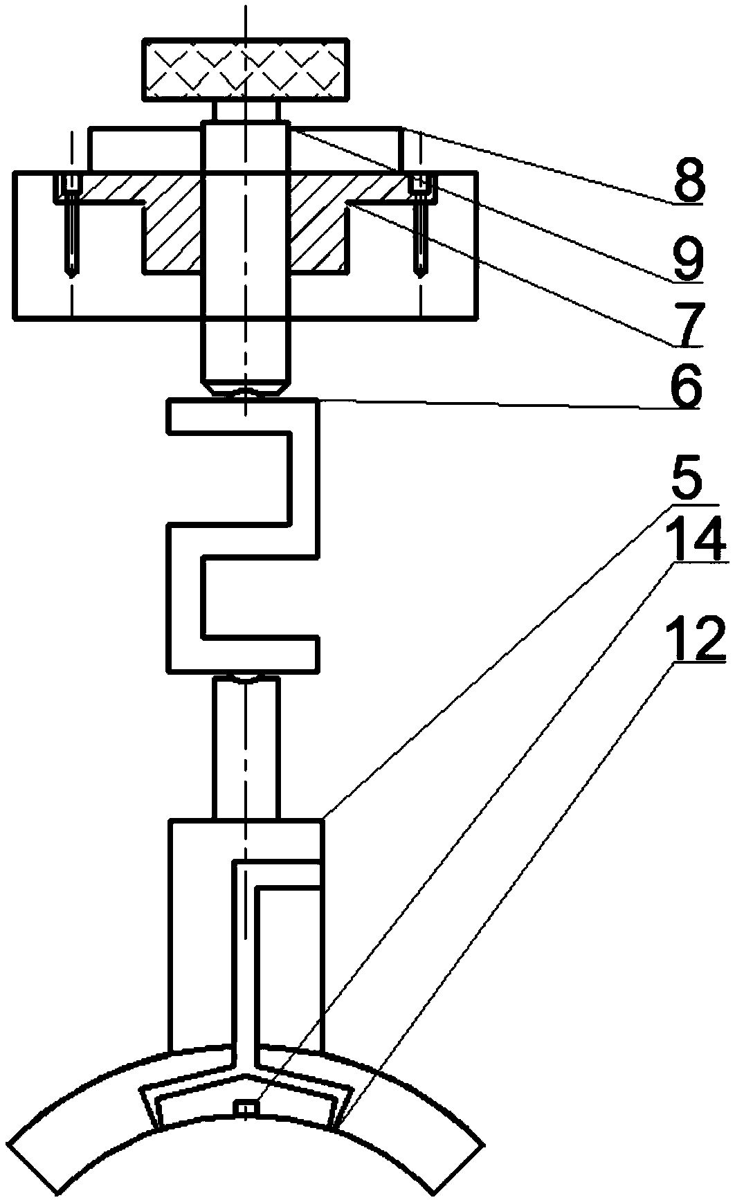
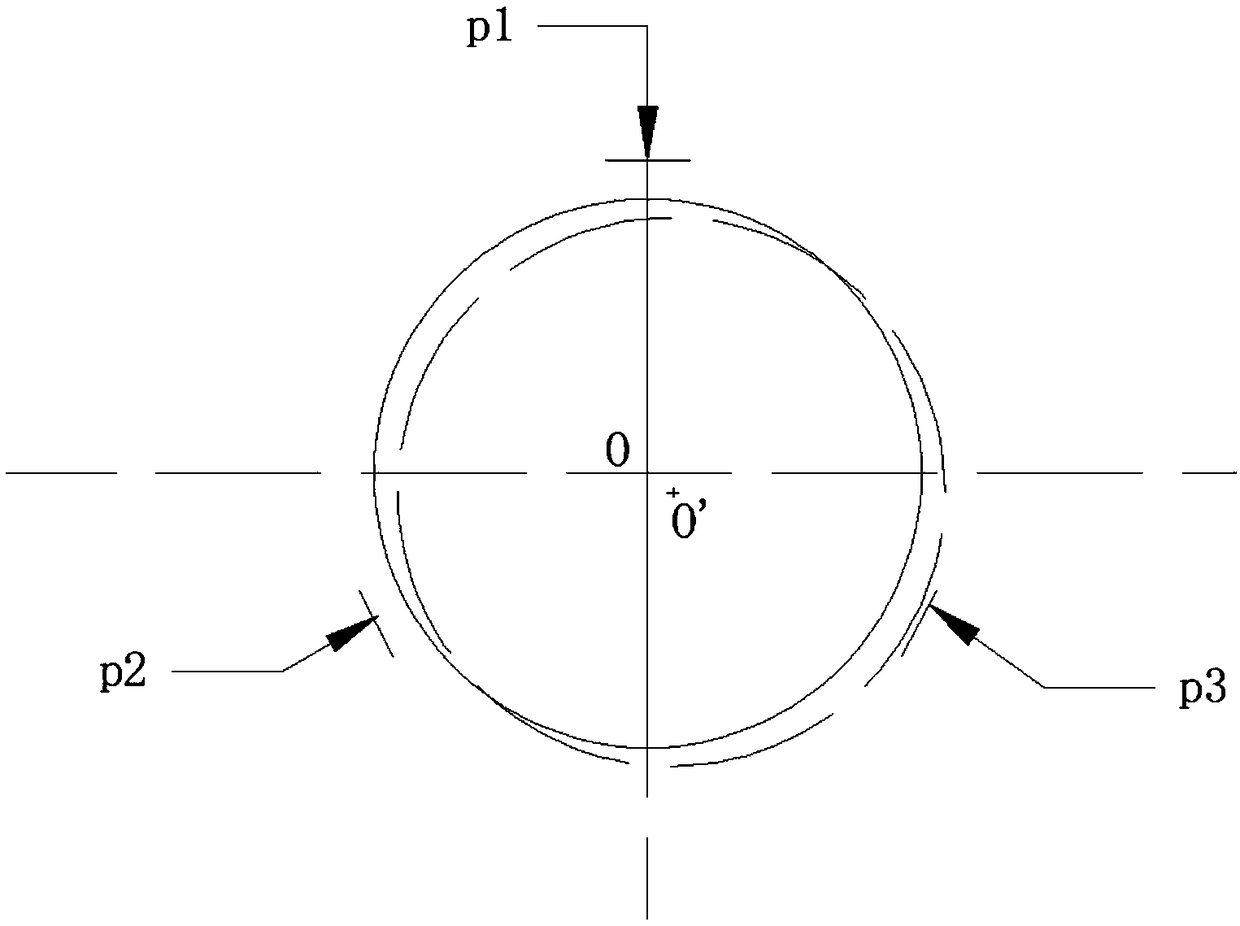
[0027] Such as figure 1 , 2 As shown in and 5, the air bearing main shaft carries the compensation device, including the fixed bracket 1, the control valve 2, the air pipe 4 and the air bearing assembly; the fixed bracket 1 is used for the support of the control valve 2 and the air bearing assembly; the fixed bracket is hollow inside Triangular, the triangle is more stable; the fixed bracket is provided with three stepped holes uniformly distributed along the circumferential direction, and the hole section with a larger diameter of the stepped holes is set outward; three air bearing components are evenly distributed along the circumferential direction. The position of the assembly corresponds to the position of the stepped hole; the air bearing assembly includes the air bearing 5, the centering adjustment rod 9, the centering adjustment rod sleeve 7, the pressure sensor 6,...


PUM


Abstract

The invention discloses an air flotation main shaft bearing compensation device and method. Bearing compensation is conducted on rotation errors of existing air flotation bearings through weights or springs, and real-time detection and bearing compensation cannot be achieved. When an air flotation main shaft generates rotation errors, a control valve adjusts the output gas pressure under the control of a controller, bearing compensation is conducted on the side, with a thin air film, of the air flotation main shaft, and adjustment of the controller is not stopped until displacement sensors ofthree air flotation support assemblies detect that the radial clearances between the air flotation support inner ends of the three air flotation support assemblies and the air flotation main shaft arethe same. The air flotation main shaft returns to the air floatation support centering position of the three air flotation support assemblies, and air flotation main shaft bearing compensation is achieved. By means of the air flotation main shaft bearing compensation device and method, real-time compensation of bearing force is achieved, and a pressure sensor displays air flotation support bearing force; and the radial clearances between the air flotation support inner ends and the air flotation main shaft are adjustable, and therefore the device can better adapt to different rotating speedsand machining of different parts.

Description

technical field [0001] The invention belongs to the technical field of precision machining, and in particular relates to an air-floating spindle bearing compensation device and a method for detecting rotation errors and bearing compensation of the air-floating spindle. Background technique [0002] With the development of science and technology, air bearings have the advantages of extremely small friction coefficient, high rotation accuracy and no pollution, and have been more and more widely used in precision machinery and measuring instruments. Air-bearing static pressure bearing embodies high-speed, high-efficiency, high-precision processing performance, and is one of the main development directions of high-precision machine tool spindles. During the working process of the air-bearing spindle, the rotation error of the spindle increases due to the feed of the cutter head, cutting force and high-speed rotation of the spindle, and the machining accuracy is difficult to guar...

Claims


Application Information

Patent Timeline
Patent Type & Authority Applications(China)
IPC IPC(8): F16C32/06
CPCF16C32/0614F16C32/067F16C32/0685
Inventor 王文魏珠珠杨贺卢科青陈占锋时光唐超锋裘荣波
Owner HANGZHOU DIANZI UNIV
Learn More