Automobile exhaust treatment ammonification system
A technology for automobile exhaust and front panel, applied in exhaust treatment, exhaust device, air quality improvement and other directions, can solve problems such as poor ammonia generation effect, and achieve the effect of lifting effect, enhancing strength and increasing temperature
- Summary
- Abstract
- Description
- Claims
- Application Information
AI Technical Summary
Problems solved by technology
Method used
Image
Examples
Embodiment 1
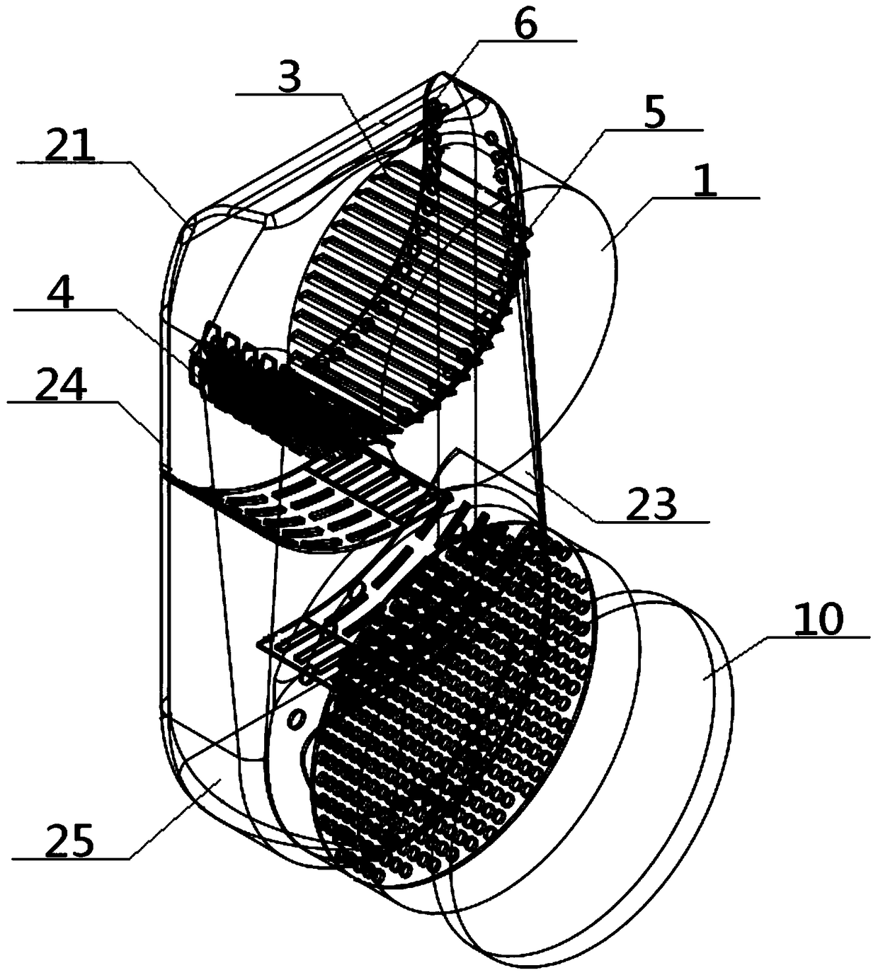
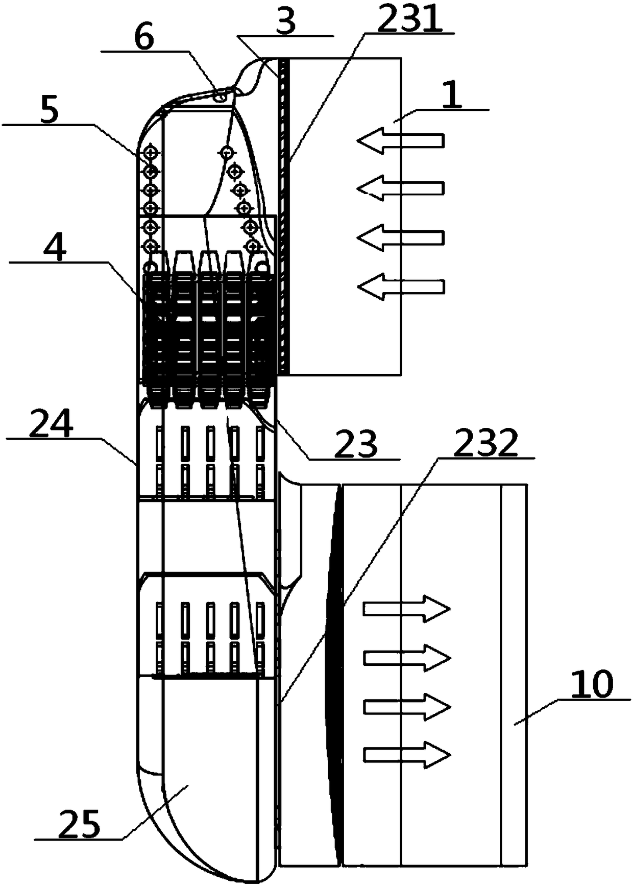
[0057] see Figure 1 to Figure 12 , an ammonia generation system for automobile exhaust treatment, comprising a DPF input end 1, an SCR output end 10, and a transition portion 2, one end of the transition portion 2 communicates with the DPF particle trapping device through the DPF input end 1, and the other end of the transition portion 2 One end communicates with the SCR catalyst device through the SCR output port 10; the transition part 2 includes a transition housing 21 and a transition chamber 22 provided inside, and the transition housing 21 includes a transition front plate 23, a transition rear plate 24 and a transition between the two There is a ring-shaped transitional side wall 25 between them, the top of the transition front plate 23 is provided with a front plate inlet 231 communicating with the DPF input end 1, and the bottom of the transition front plate 23 is provided with a front plate communicating with the SCR output end 10 The outlet 232, and the DPF input e...
Embodiment 2
[0059] Basic content is the same as embodiment 1, the difference is:
[0060] The bottom end of the arc breaker 4 is in contact with the bottom end of the diversion curved plate 5 through the gap X1 of the device plate, and the communication path between the No. 1 cavity X and the transition chamber 22 includes the arc breaker 4 and the Board gap X1. A plate mouth gap 233 is arranged between the deflector panel 3 and the front plate inlet 231, and the plate mouth gap 233 is arranged near the urea injection hole 6, and the injection direction of the urea injection hole 6 is set opposite to the arc breaker 4 . The positions near the transition front plate 23 and the transition rear plate 24 on the guide curved plate 5 are correspondingly provided with a front hole row 53 and a rear hole row 54, and the front hole row 53 and the rear hole row 54 each include a plurality of The bent plate through hole 55.
Embodiment 3
[0062] Basic content is the same as embodiment 1, the difference is:
[0063] The arc breaker 4 comprises an arc frame 41 and a plurality of vertical plate beams 42 and transverse plate beams 43 arranged inside thereof, the arc of the transverse plate beams 43 is consistent with the arc frame 41, and the adjacent transverse plate beams 43 are mutually Parallel, adjacent vertical beams 42 are parallel to each other, each horizontal beam 43 intersects all vertical beams 42, each vertical beam 42 intersects all horizontal beams 43, a single vertical beam 42 Divided by all the horizontal plate beams 43 into a plurality of successively connected horizontal sub-plates 421, the horizontal sub-plates 421 are pierced with broken pieces 44; along the direction of a single vertical plate beam 42, adjacent broken pieces 44 are arranged There is a vertical gap 45; along the direction of the single horizontal plate beam 43, a horizontal gap 46 is set between adjacent broken pieces 44. The ...
PUM
 Abstract
Description
Claims
Application Information
 - R&D Engineer
- R&D Manager
- IP Professional
- Industry Leading Data Capabilities
- Powerful AI technology
- Patent DNA Extraction
Browse by: Latest US Patents, China's latest patents, Technical Efficacy Thesaurus, Application Domain, Technology Topic, Popular Technical Reports.
© 2024 PatSnap. All rights reserved.Legal|Privacy policy|Modern Slavery Act Transparency Statement|Sitemap|About US| Contact US: help@patsnap.com


