
Fuel cell system

A fuel cell system, fuel cell technology, applied in the direction of fuel cells, circuits, electrical components, etc.

Pending Publication Date: 2019-03-15
徐煜
View PDF9 Cites 2 Cited by
  • Summary
  • Abstract
  • Description
  • Claims
  • Application Information

AI Technical Summary

Problems solved by technology

[0004] The main purpose of the present invention is to provide a kind of equipment that adopts electrolysis water to reclaim the water that proton exchange membrane fuel cell produces and carry out electrolysis reaction, and can produce fuel gas and oxidant gas that proton exchange membrane fuel cell needs, to solve the problem caused by chemical The water produced by the reaction is environmentally friendly, and the water can be recycled and reused to reduce the supply cost of fuel gas and oxidant gas

Method used


Image

  • Fuel cell system
  • Fuel cell system

Examples


Embodiment Construction

[0012] In order to make the purpose, technical features, and advantages of the present invention better understood by those in the relevant technical field and able to implement the present invention, the technical features and implementation modes of the present invention are illustrated in detail in conjunction with the attached drawings and listed here. The preferred embodiment is further explained. The drawings to be compared in the following text are schematic representations related to the characteristics of the present invention, and are not and need not be drawn completely based on actual situations. The description of the implementation of this case involves technical content familiar to those skilled in the art, and will not be described again.

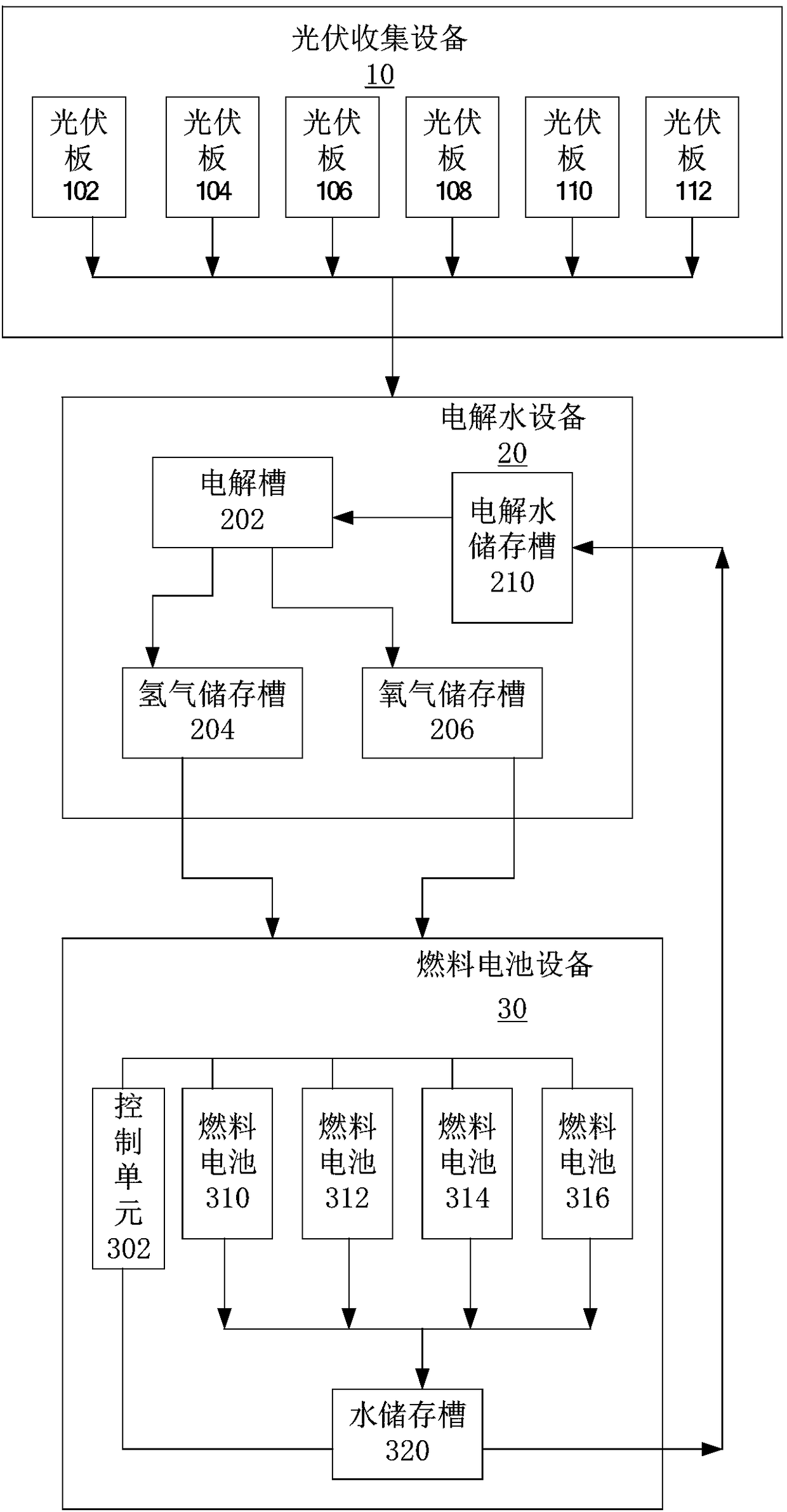
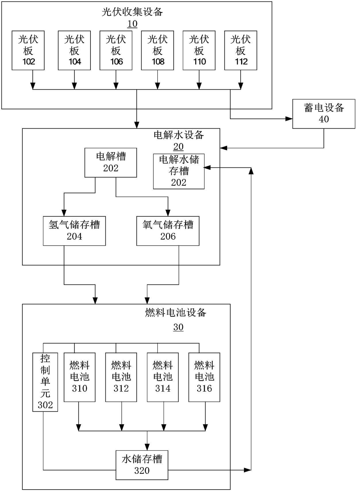
[0013] Please refer first figure 1 . figure 1 A block diagram showing a fuel cell system according to an embodiment of the present invention. in figure 1 In the fuel cell system, a photovoltaic collection device 10, a water el...


PUM


Abstract

A fuel cell system is composed of photovoltaic collecting equipment, water electrolysis equipment and fuel cell equipment, wherein the photovoltaic collecting equipment has multiple photovoltaic panels, and is used for collecting sunlight and converting light energy of the sunlight into electric energy; the water electrolysis equipment electrolyzes water according to the electric energy convertedby the photovoltaic collecting equipment, so that hydrogen and oxygen are generated; furthermore, hydrogen and oxygen are respectively stored in a hydrogen storage tank and an oxygen storage tank; thefuel cell equipment comprises a control unit and multiple fuel cells; and the control unit is used for controlling the flow of hydrogen and oxygen entering each fuel cell, so that each fuel cell generates the electric energy through hydrogen and oxygen reaction.

Description

Technical field [0001] The present invention relates to the field of fuel cells, in particular to a fuel cell system that uses photovoltaic panels to generate electricity and supplies electrolysis equipment to electrolyze water to generate hydrogen and oxygen, so as to be used as fuel cell reaction gas. Background technique [0002] The proton exchange membrane fuel cell is a power generation device that directly converts the chemical energy in fuel and oxidant into electrical energy through the electrocatalytic reaction on the electrode. When the proton exchange membrane fuel cell is working, it is necessary to continuously deliver fuel and oxidant into the proton exchange membrane fuel cell to continuously obtain electric energy, and at the same time to continuously remove the water and heat generated by the chemical reaction. Although the proton exchange membrane fuel cell has the characteristics of low operating temperature, fast start-up, and high energy conversion rate, it ...

Claims


Application Information

Patent Timeline
IPC IPC(8): H01M8/0656
CPCH01M8/0656H01M2008/1095Y02E60/50
Inventor 徐煜
Owner 徐煜
Learn More