
VFTO signal measuring device

A signal measurement and battery technology, applied in the direction of using digital measurement technology for measurement, etc., can solve the problem that the measurement equipment shows a large power consumption, the battery-powered system has limited use time, and is not enough to obtain electromagnetic disturbance statistical characteristics. Localized protection impact assessment and other problems to achieve the effect of filling the measurement gap

Inactive Publication Date: 2019-03-15
NARI TECH CO LTD +5
View PDF8 Cites 5 Cited by
  • Summary
  • Abstract
  • Description
  • Claims
  • Application Information

AI Technical Summary

Problems solved by technology

However, due to the lack of test opportunities, the test data is insufficient to obtain the statistical characteristics of electromagnetic disturbance and the impact assessment on in-situ protection
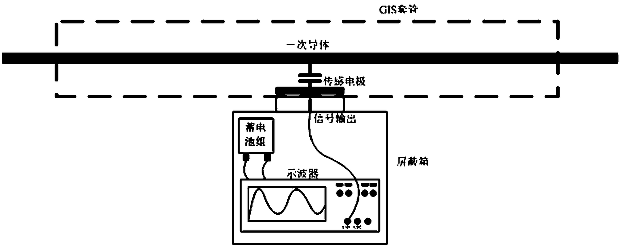
At the same time, the VFTO measurement system has some shortcomings and problems in the actual measurement. The summary is as follows: (1) Because the VFTO sensor is at the primary equipment end, the test point is located outdoors, and because a commercial-grade oscilloscope is used for measurement, its operating temperature range It cannot be used outdoors for a long time; (2) Due to the large power consumption of the waveform displayed by the measuring equipment, the battery-powered system has a limited service time, and cannot continuously observe and capture the VFTO signal waveform for a long time; (3) The measurement system can only measure the VFTO voltage signal. Measurement, cannot measure the current waveform when VFTO occurs

Method used


Image

  • VFTO signal measuring device
  • VFTO signal measuring device

Examples


Embodiment Construction

[0023] The present invention will now be further described in detail in conjunction with the accompanying drawings and embodiments. These drawings are all simplified schematic diagrams, only illustrating the basic structure of the present invention in a schematic manner, so it only shows the composition related to the present invention.

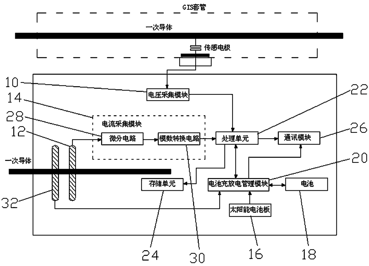
[0024] Such as figure 2 As shown, a VFTO signal measurement device includes a voltage acquisition module 10, a Rogowski coil 12, a current acquisition module 14, a solar panel 16, a battery 18, a battery charge and discharge management module 20, a processing unit 22, a storage unit 24 and a communication module 26. The Rogowski coil 12 is connected to the current acquisition module 14, the solar panel 16 and the battery 18 are connected to the battery charge and discharge management module 20, the voltage acquisition module 10, the current acquisition module 14, the battery charge and discharge management module 20, and the storage unit 24....


PUM


Abstract

The invention relates to a VFTO signal measuring device which comprises a voltage acquisition module, a Rogowski coil, a current acquisition module, a solar battery panel, a battery, a battery chargeand discharge management module, a processing unit, a storage unit and a communication module. The Rogowski coil is connected with the current acquisition module, the solar battery panel and the battery are both connected with the battery charging and discharging management module, the voltage acquisition module, the current acquisition module, the battery charging and discharging management module, the storage unit and the communication module are all connected with the processing unit, and the communication module is connected with the battery charging and discharging management module. TheVFTO signal measuring device realizes the on-line real-time monitoring of the VFTO signal, can work outdoors for a long time by utilizing a plurality of parallel power supply modes, and continuously observes and captures the waveform of the VFTO signal; inputting broadband to Rogowski coil to measure the VFTO current signal so as to make up for the blank of VFTO current signal measurement; the broadband signal data on the electric transmission line is provided in real time, and a data signal source is provided for other applications.

Description

technical field [0001] The invention relates to the field of power system automation, in particular to a VFTO signal measuring device. Background technique [0002] The State Grid Corporation of China has identified the local application of relay protection as the development direction of protection technology. The local application has the advantages of reducing the length of the secondary electric (optical) cable, optimizing the design of the secondary circuit, reducing land use and building area, and saving investment. . Since the in-situ protection device is installed near the primary equipment, its operating environment is more severe, especially the VFTO (Very Fast Transient Over-voltage) transient electromagnetic disturbance caused by the operation of the isolation switch of the GIS substation has large amplitude, wide frequency, and multi-pulse and other characteristics, causing serious interference to in-situ protection equipment. In order to study the impact of V...

Claims


Application Information

Patent Timeline
IPC IPC(8): G01R19/25
CPCG01R19/25
Inventor 邹志杨周华良夏雨汪世平张晓莉赵军刘慧海庞福滨邓庆
Owner NARI TECH CO LTD
Learn More