Yarn waxing device for textile machinery

A technology for textile machinery and yarn, which is applied in the field of yarn waxing devices for textile machinery, which can solve the problems of affecting the quality of yarn use, yarn quality, and uneven waxing, so as to improve the waxing effect and improve contact area, the effect of improving firmness

Active Publication Date: 2019-03-15
桂林市盛茏纺织有限公司
View PDF8 Cites 6 Cited by
  • Summary
  • Abstract
  • Description
  • Claims
  • Application Information

AI Technical Summary

Problems solved by technology

Yarn sticking tends to occur during yarn de-heating and manufacturing process. For example, exported yarn is prone to mildew after long-term transportation, which will affect the quality of yarn.
[0003] A fastening type textile yarn waxing mechanism announced by the State Intellectual Property Office of China (application number: 201710222818.1, publication number: CN106865358A, application date: 2017.04.07), including a first waxing device and a second waxing device , the first waxing device and the second waxing device both include a motor, a rotating shaft, a fixed groove, a wax plate, a limit plate, a spring, a support plate, a guide rod, a fixed rod and a sliding device, and the output shaft of the motor is fixedly connected to the rotating shaft , the guide rod is provided with a fixing groove, the rotating shaft is fixedly connected with the side wall of the fixing groove through the bearing, the wax plate is fixed on the rotating shaft and is located inside the fixing groove, the guide rod is located at the lower end of the fixing groove to fix the limit plate, the guide rod is covered with a spring, the spring One end of the spring is fixedly connected with the limit plate, and the other end of the spring is fixedly connected with the support plate. Through the force of the spring on the limit plate, the friction between the wax plate and the yarn can be increased, thereby enhancing the waxing effect, and Through two waxing devices, the yarn is waxed at multiple angles, but this device is easy to cause waste of wax, and there will be uneven waxing, which will affect the quality of the yarn

Method used


Image

  • Yarn waxing device for textile machinery
  • Yarn waxing device for textile machinery
  • Yarn waxing device for textile machinery

Examples


Embodiment Construction

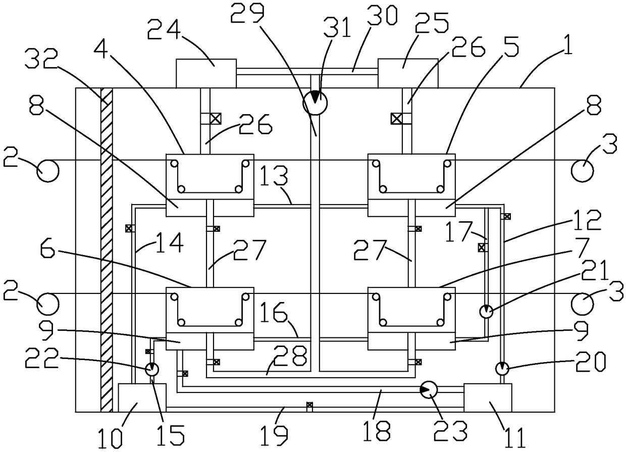
[0030] Such as Figure 1 to Figure 5 As shown, it is a yarn waxing device for textile machinery of the present invention, which includes a box body 1, a yarn delivery roller 2 and a yarn take-up roller 3, and two yarn delivery rollers 2 and two yarn take-up rollers 3 are located on the side of the box body 1. On the left and right sides, the yarn passes through the box body 1 through the yarn feeding roller 2 and is connected to the yarn receiving roller 3. The first main waxing box 4, the first auxiliary waxing box 5, and the second main upper waxing box are arranged in the box body 1. The wax box 6, the second auxiliary wax box 7, the wax supply device and the hot and cold water system, the second main wax box 6 and the second auxiliary wax box 7 are respectively located on the first main wax box 4 and the first auxiliary Below the waxing box 5, and the first main waxing box 4, the first auxiliary waxing box 5, the second main waxing box 6 and the second auxiliary waxing box...


PUM


Abstract

The invention discloses a yarn waxing device for textile machinery. The yarn waxing device comprises a box body, yarn feeding rollers and yarn receiving rollers; the box body is internally provided with a first main waxing box, a first auxiliary waxing box, a second main waxing box, a second auxiliary waxing box, a wax supply device and a cold and hot water system; the wax supply device is separately communicated with the first main waxing box, the first auxiliary waxing box, the second main waxing box and the second auxiliary waxing box; the cold and hot water system is separately connected to the first main waxing box, the first auxiliary waxing box, the second main waxing box and the second auxiliary waxing box; baffles are arranged between the first main waxing box and the yarn feedingrollers and between the second main waxing box and the yarn feeding rollers. The yarn waxing device is simple in structure and high in practicability, not only are the waxing effect and quality of yarn improved, but also recycling of wax can be realized, waste of the wax is reduced, the wax is transformed between a solid state and a liquid state, and the automation degree of the yarn waxing device is greatly increased.

Description

technical field [0001] The invention relates to a yarn waxing device for textile machinery. Background technique [0002] The gloss and elasticity of the waxed and non-waxed fabrics are completely different. After waxing, the pinholes pass through smoothly, the tension is reduced, and the broken ends are reduced. The fabric is a bit like the softness and feel of satin. Yarn sticking tends to occur in the process of yarn cooling and manufacturing. For example, the exported yarn is prone to mildew after a long period of transportation, which will affect the quality of the yarn. [0003] A fastening type textile yarn waxing mechanism announced by the State Intellectual Property Office of China (application number: 201710222818.1, publication number: CN106865358A, application date: 2017.04.07), including a first waxing device and a second waxing device , the first waxing device and the second waxing device both include a motor, a rotating shaft, a fixed groove, a wax plate, a l...

Claims


Application Information

Patent Timeline
IPC IPC(8): D01H13/30D02J3/18
CPCD01H13/308D02J3/18
Inventor 赵城
Owner 桂林市盛茏纺织有限公司
Why Eureka
Try Eureka