
Flushing device for leaking liquid at periphery of drainage tube

A flushing device and drainage tube technology, which is applied in the medical field, can solve problems such as prolonged hospitalization time, difficult cleaning of wounds, prolonged hospitalization time, etc., and achieve the effects of reducing nursing workload, convenient flushing and disinfection, and reducing hospitalization costs

Inactive Publication Date: 2019-03-15
刘方峰
View PDF4 Cites 2 Cited by
  • Summary
  • Abstract
  • Description
  • Claims
  • Application Information

AI Technical Summary

Problems solved by technology

Due to the need to wear the tube for a long time, or to replace the drainage device repeatedly, a large amount of erosive digestive fluid leaks out, sometimes eroding the tissue near the skin around the tube, resulting in tissue ulcers, bleeding, infection, and the leakage of the flushing fluid also leads to incisions and around the tube Contamination of excipients increases patient pain, nursing management workload, prolongs hospital stay, slows recovery of patients, prolongs hospital stay, and even causes serious consequences due to infection around the tube and formation of subcutaneous abscess cavity
Leakage and infection around the drainage tube are mostly caused by increasing the number of sterile gauze dressing changes and replacing antibacterial auxiliary materials, which cannot fundamentally solve the problem
Especially at night, the soaked dressing increases the pain of the patient, and the skin is corroded and the pain is severe
Moreover, the existing methods have poor drainage effects, local digestive juices gather, tissue soaks, and healing is difficult; wounds are difficult to clean, which is not conducive to wound management and rehabilitation

Method used

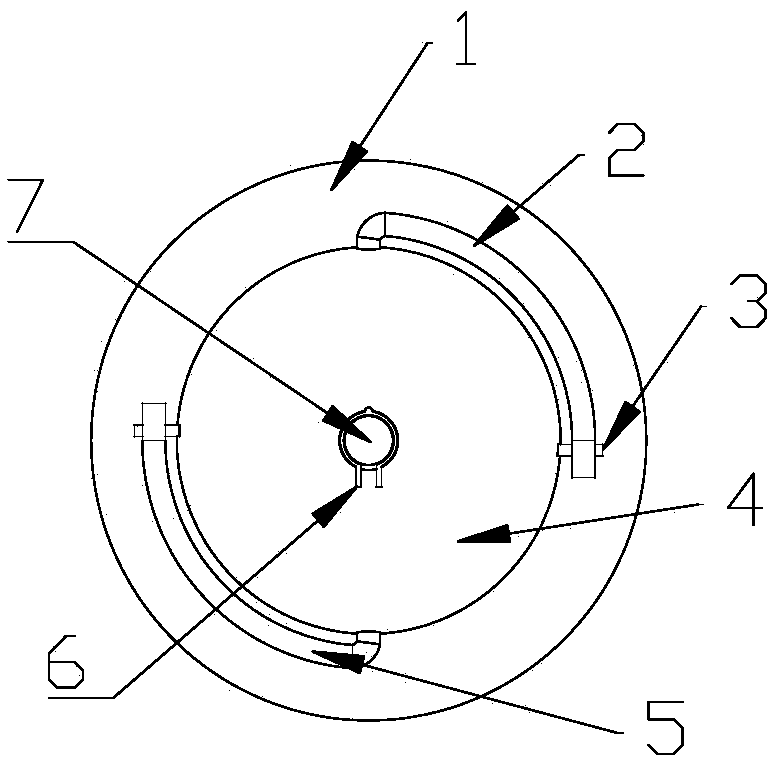
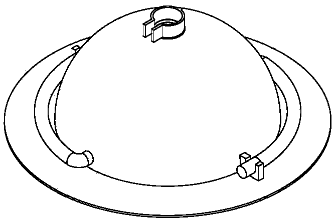
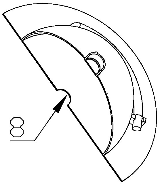

Image

  • Flushing device for leaking liquid at periphery of drainage tube
  • Flushing device for leaking liquid at periphery of drainage tube
  • Flushing device for leaking liquid at periphery of drainage tube

Examples


Embodiment Construction

[0023] Embodiments of the present invention are described in detail below, examples of which are shown in the drawings, wherein the same or similar reference numerals designate the same or similar elements or elements having the same or similar functions throughout. The embodiments described below by referring to the accompanying drawings are exemplary and are only used to explain the present invention, but should not be construed as a limitation of the present invention. Further description is given below in conjunction with the accompanying drawings.

[0024] The present invention provides a flushing device for leaking liquid from the periphery of a drainage tube, comprising: a base plate 1, a through hole 8 for passing through the drainage tube is arranged in the middle of the base plate 1, a drainage box 4 is arranged on the base plate 1, and the drainage box 4 is a The hemispherical transparent plexiglass shell, the side of the drainage box 4 is provided with a flushing h...


PUM


Abstract

The invention discloses a flushing device for a leaking liquid at the periphery of a drainage tube. The device comprises a chassis, wherein a through hole used for allowing the drainage tube to run through is formed in the middle of the chassis, a drainage box is arranged on the chassis, the side face of the drainage box is provided with a flushing hole and a draining hole, the top end of the drainage box is provided with a drainage hole used for allowing the drainage tube to run through, the drainage hole is internally provided with a valve, and the outer side of the drainage hole is providedwith a pipe clamp. When a leaking liquid occurs at the periphery of an alimentary canal fistula, the leaking liquid can be stored in the drainage box and cannot be in contact with the skin, thereby reducing the corrosion of the leaking liquid on the skin and the tissue, and greatly reducing or avoiding the infection around the drainage tube. The device is provided with a flushing tube and a draining tube, so that flushing and disinfection are convenient, and the workload of nursing is reduced. The average time in hospital is reduced, the cost in hospital is reduced, and the comfort of a patient in hospital is improved.

Description

technical field [0001] The invention relates to a flushing device for peripheral leakage of a drainage tube, belonging to the field of medicine. Background technique [0002] Many digestive tract tumors, such as esophageal cancer, gastric fundus and cardia cancer, colon cancer, pancreatic cancer, and bile duct malignant tumors, require surgical resection and reconstruction of the digestive tract. Once gastrointestinal fistula or infection occurs after operation, it is necessary to strengthen wound drainage. Due to the need to carry the tube for a long time, or to replace the drainage device repeatedly, a large amount of erosive digestive juice leaks out, sometimes eroding the tissue near the skin and surrounding the tube, causing tissue ulcers, bleeding, infection, and leakage of irrigation fluid. The contamination of accessories increases the pain of patients, increases the workload of nursing management, prolongs the hospitalization time, makes the patient recover slowly,...

Claims


Application Information

Patent Timeline
IPC IPC(8): A61M1/00A61M3/02
CPCA61M1/0001A61M1/0023A61M1/0058A61M3/0279A61M1/84A61M1/85A61M1/90
Inventor 刘方峰
Owner 刘方峰
Learn More