Model-free adaptive control method of linear motor servo system
A model-free adaptive, linear motor technology, applied in the direction of AC motor control, control system, electrical components, etc., can solve the problem of good robustness
- Summary
- Abstract
- Description
- Claims
- Application Information
AI Technical Summary
Problems solved by technology
Method used
Image
Examples
Embodiment 1
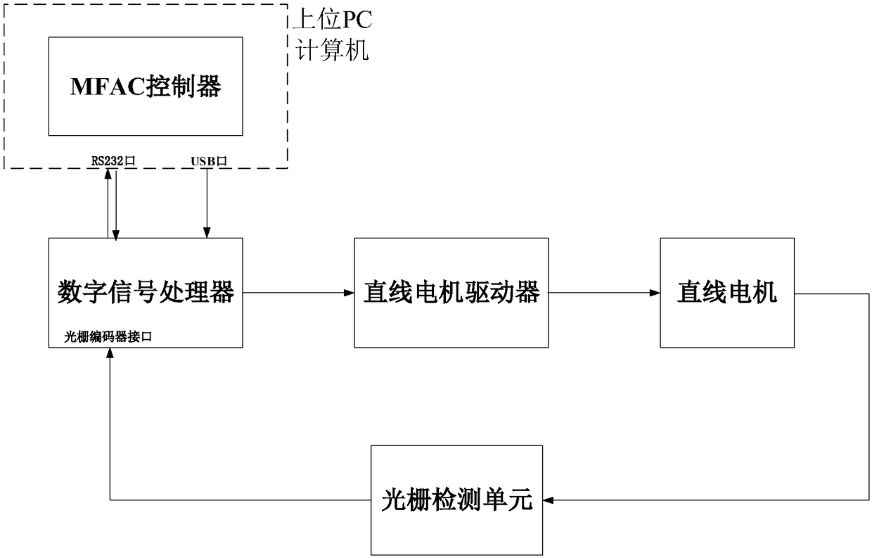
[0095] figure 1 It is the composition and connection diagram of applying the model-free adaptive control method to the tool feed linear motor servo system. The system consists of an upper PC computer, MFAC controller, digital signal processor, linear motor driver, linear motor, and grating detection unit;
[0096] The specific connection method is as follows:
[0097] Step I: In the upper PC computer, utilize the Simulink software in cSPACE to build the MFAC control scheme;
[0098] Step II: download the algorithm control signal u(k) code to the DSP control card of the digital signal processor through the USB port of the upper PC computer;
[0099] Step III: The linear motor servo driver realizes the communication with the digital signal processor and sends the start-stop signal of the motor through the RS232 interface of the upper PC computer;
[0100] Step IV: the DSP control card converts the downloaded control signal u(k) through D / A to control the linear motor driver; ...
Embodiment 2
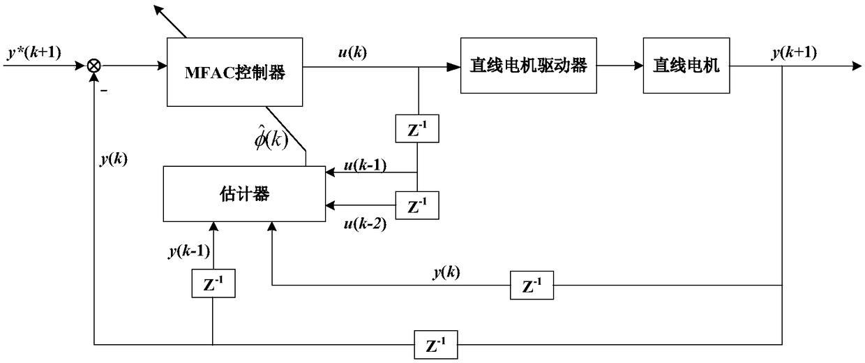
[0107] This embodiment elaborates in detail the control structure when the model-free adaptive control scheme of the present invention is implemented in the linear motor servo system, as figure 2shown.
[0108] The specific implementation process is as follows:
[0109] step 1):
[0110] The linear motor servo system meets the following three conditions:
[0111] Condition 4.1 The input voltage and output position are observable and controllable, that is, for the expected sinusoidal position output signal of a given amplitude (within the allowable range), there must be a voltage input signal (within the allowable range of the motor), so that the linear motor Driven by this voltage signal, the position output follows the sinusoidal output expected by the system.
[0112] Condition 4.2 The partial derivative of the unknown nonlinear function of the linear servo system with respect to the current voltage control input u(k) is continuous. That is, the input control voltage is...
Embodiment 3
[0123] This embodiment elaborates in detail the experimental results when the model-free adaptive control scheme of the present invention is implemented in a linear motor servo system.
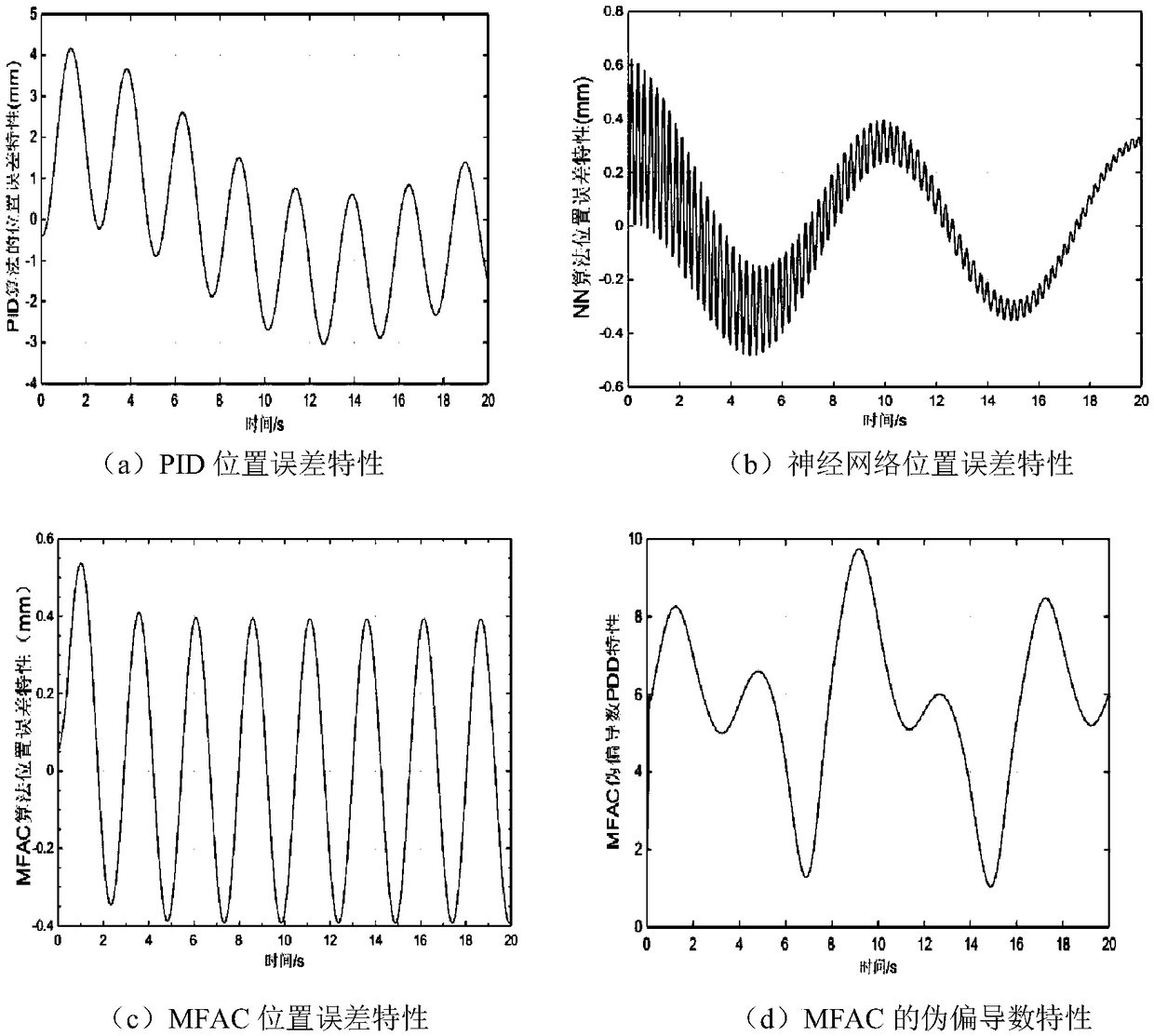
[0124] Such as image 3 As shown, the present embodiment is a comparison of PID, neural network and MFAC scheme characteristics of the present invention, three kinds of control schemes are all provided with the same sinusoidal input signal frequency is increased to 1Hz by 0.2Hz, the amplitude selection is 90mm, and the sampling period is all selected as 0.005s.
[0125] In this experiment, the position error characteristics when the PID parameters are adjusted to the best (1, 42, 0) are as follows: image 3 As shown in (a), the maximum error is about 4mm, and the error is always in a state of constant change, and the error is large, and the control effect is not good enough. image 3 (b) in (b) adopts the neural network control method, and the number of training times is set to 20,000 times ...
PUM
 Abstract
Description
Claims
Application Information
 - R&D
- Intellectual Property
- Life Sciences
- Materials
- Tech Scout
- Unparalleled Data Quality
- Higher Quality Content
- 60% Fewer Hallucinations
Browse by: Latest US Patents, China's latest patents, Technical Efficacy Thesaurus, Application Domain, Technology Topic, Popular Technical Reports.
© 2025 PatSnap. All rights reserved.Legal|Privacy policy|Modern Slavery Act Transparency Statement|Sitemap|About US| Contact US: help@patsnap.com


