
Automobile anti-collision radar array antenna and circuit board provided with the array antenna

A radar array and array antenna technology, which is applied in the direction of printed circuits, antennas, circuits, etc. connected by non-printed electrical components, can solve the problems of microstrip antenna array size increase, beam width, and low gain, and achieve improved reception Gain, achieve volume, flexible installation effect

Active Publication Date: 2019-03-12
广州合智瑞达科技有限公司
View PDF9 Cites 3 Cited by
  • Summary
  • Abstract
  • Description
  • Claims
  • Application Information

AI Technical Summary

Problems solved by technology

In order to ensure the working distance of the receiving antenna, high antenna gain is required, and the size of the microstrip antenna array increases, resulting in an increase in the array spacing between the two receiving array antennas, resulting in 2π ambiguity that affects the angle measurement range
With a single linear array antenna, the array spacing λ / 2 can meet the angle measurement range, but the gain is low and the beam is wide, resulting in more detection targets, increasing the amount of calculation and processing complexity

Method used


Image

  • Automobile anti-collision radar array antenna and circuit board provided with the array antenna
  • Automobile anti-collision radar array antenna and circuit board provided with the array antenna
  • Automobile anti-collision radar array antenna and circuit board provided with the array antenna

Examples


Embodiment Construction

[0031] The following will clearly and completely describe the technical solutions in the embodiments of the present invention with reference to the accompanying drawings in the embodiments of the present invention. Obviously, the described embodiments are only some, not all, embodiments of the present invention. Based on the embodiments of the present invention, all other embodiments obtained by persons of ordinary skill in the art without making creative efforts belong to the protection scope of the present invention.

[0032] It should be noted that when a component is said to be "fixed" to another component, it can be directly on the other component or there can also be an intervening component. When a component is said to be "connected" to another component, it may be directly connected to the other component or there may be intervening components at the same time. When a component is said to be "set on" another component, it may be set directly on the other component or t...


PUM


Abstract

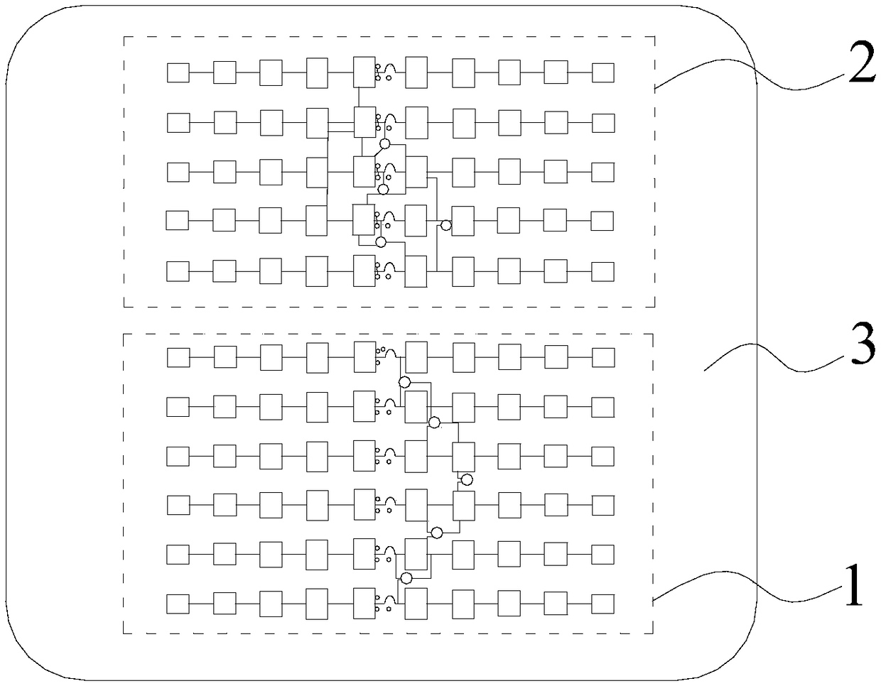
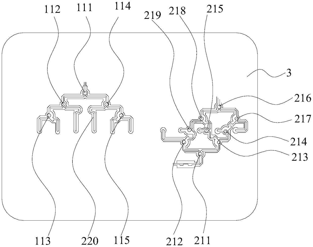
The invention belongs to the field of radar technology, and discloses an automobile anti-collision radar array antenna, comprising at least one transmitting antenna and at least two receiving antennas, wherein a transmitting array and a transmitting power divider are arranged in the transmitting antenna, and a receiving array and a receiving power divider are arranged in each receiving antenna. The invention further discloses a circuit board provided with the array antenna, comprising the automobile anti-collision radar array antenna, wherein the automobile anti-collision radar array antenna is arranged on a dielectric board. The automobile anti-collision radar array antenna disclosed by the invention is capable of providing a high antenna gain, having no blind zone in beam coverage, and having a wide angle measurement range and a low sidelobe.

Description

technical field [0001] The invention belongs to the technical field of radar, and in particular relates to an automobile anti-collision radar array antenna and a circuit board provided with the array antenna. Background technique [0002] The 24GHz millimeter-wave radar is used for forward collision avoidance of automobiles. It needs to detect the targets in front of the lane and the moving targets that intend to enter the lane at short range. According to the book "Radar Principles" edited by Ding Lufei, the radar operating distance is related to the gain of the transmitting and receiving antenna. Angle measurement generally uses the multi-receiving antenna phase method, the phase difference The relationship with the measurement angle θ is [0003] [0004] Where λ is the wavelength of the radar, d is the spacing of the linear array, and the angle measurement range is related to the spacing of the array. [0005] In order to achieve long-distance and wide-beam covera...

Claims


Application Information

Patent Timeline
Patent Type & Authority Applications(China)
IPC IPC(8): H01Q23/00H01Q21/00H01Q21/06H01Q1/48H01Q1/50H01Q1/32H05K1/16H05K1/18
CPCH01Q1/3233H01Q1/48H01Q1/50H01Q21/0006H01Q21/061H01Q23/00H05K1/16H05K1/18
Inventor 梁卫祖刘培育叶常青植宝辉刘虎
Owner 广州合智瑞达科技有限公司
Learn More