
Distributed emitter follower amplifier

An amplifier, distributed technology, applied in the direction of amplifier, amplifier combination, amplifier input/output impedance improvement, etc., can solve the problem of signal phase is no longer the same, increase the complexity of circuit structure, can not obtain gain, etc., to simplify circuit structure, The effect of improving high frequency gain and improving efficiency

Pending Publication Date: 2019-03-08
SUZHOU INNOTION TECH
View PDF26 Cites 2 Cited by
  • Summary
  • Abstract
  • Description
  • Claims
  • Application Information

AI Technical Summary

Problems solved by technology

But on the one hand, it increases the complexity of the circuit structure and reduces the efficiency of the distributed amplifier; on the other hand, only half of the output signal of each transistor in the circuit structure is transmitted to the right to become a useful signal, while to the left The reverse wave is absorbed by the impedance of the base and collector, further reducing the efficiency of the distributed amplifier
In addition, as the operating frequency of the circuit increases, the loss and parasitic parameters of the artificial transmission line cannot be ignored, and the phases of the signals at the output of the transistor are no longer the same, and the maximum gain cannot be obtained after superposition

Method used


Image

  • Distributed emitter follower amplifier
  • Distributed emitter follower amplifier
  • Distributed emitter follower amplifier

Examples


Embodiment Construction

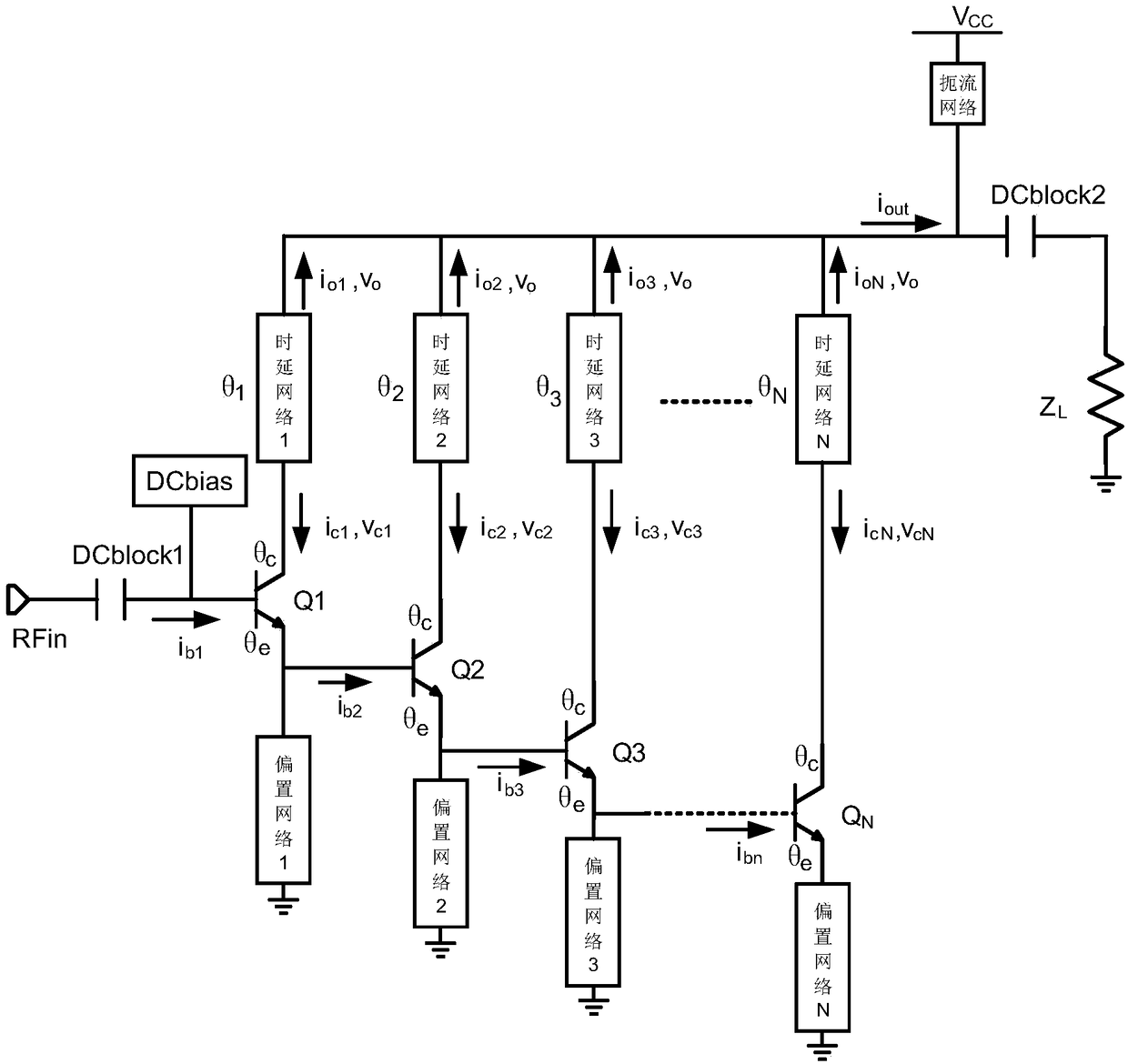
[0026] The core of the present invention is to provide a distributed emitter-follower amplifier without base / gate artificial transmission lines, which simplifies the circuit structure; without base / gate absorbing resistors and collector / drain absorbing resistors, so that output signals at all levels Both will be converted into useful signals, thereby improving the efficiency of the distributed emitter follower amplifier; in addition, with the increase of the operating frequency of the circuit structure, the output signals of the transistors at all levels are phase compensated, so that the final output signal phase is the same , which increases the high-frequency gain.

[0027] In order to make the purpose, technical solutions and advantages of the embodiments of the present invention clearer, the technical solutions in the embodiments of the present invention will be clearly and completely described below in conjunction with the drawings in the embodiments of the present invent...


PUM


Abstract

The invention discloses a distributed emitter follower amplifier. N stages of transistors and N bias networks use an emitter follower amplifier connection method; third ends (collectors or drains) ofeach stage of the transistors are also provided with a time-delay network; each stage of time-delay network compensates the phase of an output signal of the third end of the respective stage field-effect tube, so that the output signals of second ends of each stage of the time-delay network have the same phase, and the maximum gain can be obtained by superimposing the output signals of each stageof the transistors. The circuit structure is simplified because no base / gate artificial transmission line is existed; no base / gate absorption resistor and no collector / drain absorption resistor are existed, so that the output signal of each stage is converted into a useful signal, and the efficiency of the distributed emitter follower amplifier is improved; moreover, in the circuit structure, as the operating frequency increases, the output signals of the transistors of each stage are phase compensated, so that the final output signals have the same phase, and the high-frequency gain is improved.

Description

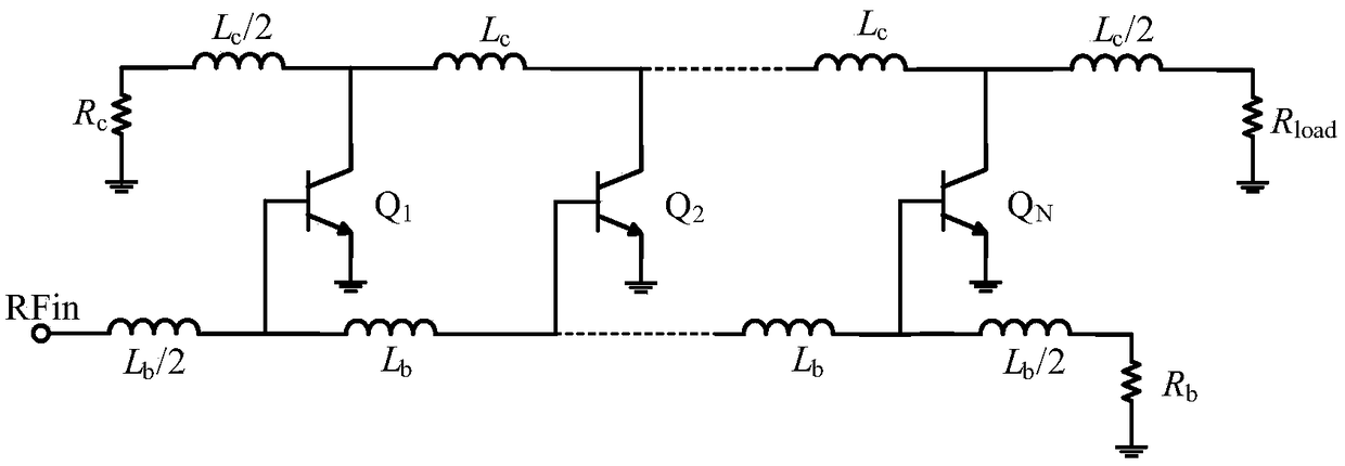
technical field [0001] The invention relates to the technical field of distributed amplifiers, in particular to a distributed emitter follower amplifier. Background technique [0002] The principle of the traditional distributed amplifier is to divide the large-signal active device into small devices, and use the parasitic capacitance of the inductor and the transistor to form an artificial transmission line. These transistors are cascaded through the artificial transmission line, which reduces the influence of the parasitic parameters of the transistor on the performance of the amplifier. And through these transistors, the input signal is amplified and coupled to the output transmission line through the transistor, which breaks through the limitation of the gain-bandwidth product, and can obtain a relatively large flat gain in the range of multiplication. [0003] Please refer to figure 1 , taking a bipolar transistor as an example, figure 1 It is a structural schematic d...

Claims


Application Information

Patent Timeline
Patent Type & Authority Applications(China)
IPC IPC(8): H03F1/56H03F3/68
CPCH03F1/565H03F3/68
Inventor 高怀田婷蔡士琦王锋丁杰
Owner SUZHOU INNOTION TECH
Learn More