
Novel laser sensor package structure

A laser sensor and packaging structure technology, applied in lasers, laser parts, semiconductor lasers, etc., can solve the problems of small VCSEL, glue overflow, inconvenient installation, etc., to achieve easy installation and use, improve yield, and accurate induction. Effect

Pending Publication Date: 2019-03-08
DONGGUAN WANGFU ELECTRONICS
View PDF0 Cites 9 Cited by
  • Summary
  • Abstract
  • Description
  • Claims
  • Application Information

AI Technical Summary

Problems solved by technology

[0003] However, most vertical cavity surface emitting lasers on the market today have the following disadvantages when they are applied to the sensor field: First, when the VCSEL is installed and used, the bottom of the diffractive optical element DOE is directly pasted on the base by glue, there will be glue overflow, Defects such as offset and inclination prevent the laser beam from being emitted perpendicular to the diffractive optical element DOE. Large deviations lead to a decrease in accuracy and cannot meet the needs of face recognition and 3D sensing. When there are defects such as chip damage and diffractive optical element DOE deviation, it is difficult to disassemble and cannot be repaired; third, the VCSEL is small in size, inconvenient to install, and lacks versatility in use, so it cannot be flexibly applied to different places

Method used


Image

  • Novel laser sensor package structure
  • Novel laser sensor package structure
  • Novel laser sensor package structure

Examples


Embodiment Construction

[0022] Below in conjunction with accompanying drawing, the specific embodiment of the present invention is described further:

[0023] In the description of the present invention, it should be noted that the terms "center", "upper", "lower", "left", "right", "vertical", "horizontal", "inner", "outer" etc. The indicated orientation or positional relationship is based on the orientation or positional relationship shown in the drawings, and is only for the convenience of describing the present invention and simplifying the description, rather than indicating or implying that the indicated position or element must have a specific orientation, and must have a specific orientation. construction and operation, therefore, should not be construed as limiting the invention.

[0024] In the description of the present invention, it should be noted that unless otherwise specified and limited, the terms "installation", "connection" and "connection" should be understood in a broad sense, for...


PUM


Abstract

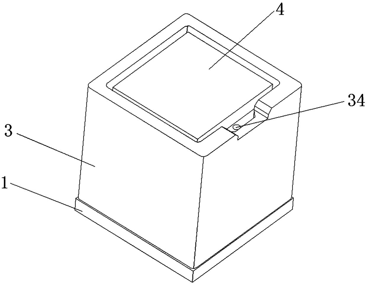
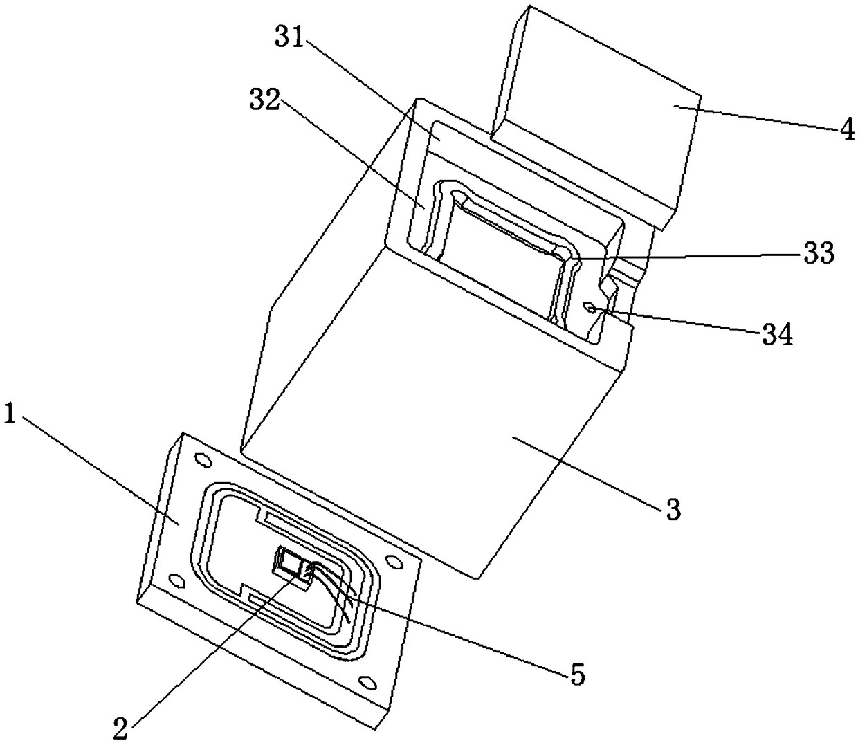
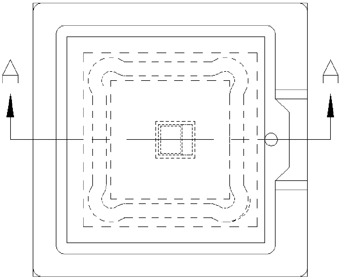
The invention relates to a laser sensor package structure. The laser sensor package structure comprises a PCB substrate, a vertical-cavity surface-emitting laser chip, a base, and a diffractive optical element (DOE), wherein the vertical-cavity surface-emitting laser chip is attached to the PCB substrate, the base is installed above the PCB substrate, the vertical-cavity surface-emitting laser chip is at the lower part inside the base, a placement cavity for placing the DOE is arranged above the base, the bottom of the placement cavity is provided with a glue tank for pasting the DOE through glue, a flange higher than the bottom of the glue tank is formed inside the glue tank, and the DOE is placed in the placement cavity and then is pasted and fixed through glue in the glue tank. The gluetank and the flange cooperate with each other so as to prevent glue overflow, deviation and inclination, and laser emitted by the chip is guaranteed to be emitted vertical to the DOE, use demands like human face recognition and 3D sensing are met, and air holes can release expansion gas effectively so as to prevent base cracking to cause DOE inclination.

Description

technical field [0001] The invention relates to the field of vertical cavity surface emitting lasers, in particular to a novel laser sensor packaging structure. Background technique [0002] Vertical-Cavity Surface-Emitting Laser (Vertical-Cavity Surface-Emitting Laser, referred to as VCSEL, also translated as vertical resonant surface-emitting laser) is a semiconductor whose laser is emitted perpendicular to the top surface. It is different, because VCSEL is more advanced than edge-emitting laser, so with the rapid development of technology, the in-depth research of VCSEL and the expansion of application requirements, VCSEL not only plays an increasingly important role in mobile phones, consumer electronics and other fields, It is also used in face recognition, 3D sensing, gesture detection and VR (virtual reality) / AR (augmented reality) / MR (mixed reality), etc. [0003] However, most vertical cavity surface emitting lasers on the market today have the following disadv...

Claims


Application Information

Patent Timeline
IPC IPC(8): H01S5/022
CPCH01S5/0225H01S5/023H01S5/0233H01S5/0235H01S5/02325
Inventor 莫林喜黄河其他发明人请求不公开姓名
Owner DONGGUAN WANGFU ELECTRONICS
Learn More