Radiator water feeding chamber diversion device

A shunt device and radiator technology, applied in the direction of machine/engine, engine components, engine cooling, etc., can solve the problems of reducing the heat exchange performance of the radiator, affecting the stability of the whole machine, and unsatisfactory heat dissipation effect, so as to reduce the dwell time. time, ensuring stability, avoiding the effect of non-uniformity

Pending Publication Date: 2019-03-08
XUZHOU XUGONG ROAD CONSTR MACHINERY
View PDF0 Cites 0 Cited by
  • Summary
  • Abstract
  • Description
  • Claims
  • Application Information

AI Technical Summary

Problems solved by technology

[0002] Traditional vehicles mostly use the engine as the power source. During the working process, fuel combustion releases a large amount of heat, part of which is used to do work, and part of it needs to be dissipated through the radiator. If the heat dissipation effect of the radiator is not ideal, it will cause high temperature in the engine. If the engine is damaged, in order to ensure the stability of the vehicle, it is necessary to dissipate the heat that needs to be exchanged through the radiator in time. In order to realize the energy saving of the whole machine system, it is particularly important to improve the heat exchange efficiency of the radiator.
[0003] At present, in the process of heat exchange, radiators and fans are usually used for heat exchange. The radiator usually contains an upper water chamber to store the hot water flowing in from the engine, and then the hot water flows into the lower water chamber through the core channel to realize heat exchange. Due to the certain pressure of the engine water outlet, the engine hot water cannot flow into the core channel in time after entering the upper water chamber, and even forms a turbulent state inside the upper water chamber, which reduces the heat transfer performance of the radiator and affects the overall performance of the machine. stability

Method used


Image

  • Radiator water feeding chamber diversion device
  • Radiator water feeding chamber diversion device
  • Radiator water feeding chamber diversion device

Examples


Embodiment Construction

[0024] The technical scheme of the present invention will be described in further detail below in conjunction with the accompanying drawings and specific embodiments, so that those skilled in the art can better understand the present invention and implement it, but the examples given are not intended to limit the present invention.

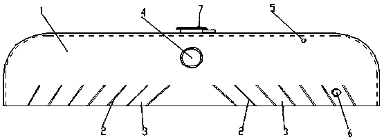
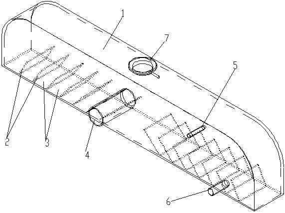
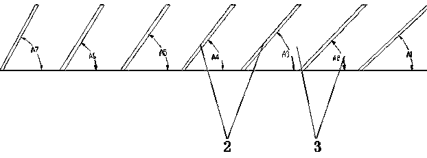
[0025] Such as figure 1 , figure 2 and image 3 As shown, the diverter device for the upper water chamber of the radiator of the present invention includes a splitter partition 2 arranged in the upper water chamber 1 of the radiator, a splitter tank 3, a radiator water inlet 4, a degassing port 5, a water replenishment port 6 and a filling Port 7 and so on. The hot water flowing in from the engine enters the radiator upper water chamber 1 from the radiator water inlet 4 . Multiple shunt partitions 2 are evenly arranged in the radiator upper water chamber 1 at equal intervals, and are arranged symmetrically on both sides of the radiator water i...


PUM


Abstract

The invention discloses a radiator water feeding chamber diversion device. The radiator water feeding chamber diversion device is characterized by comprising a plurality of diversion separation platesarranged in the upper water feeding chamber and a diversion channel formed between every two adjacent diversion separation plates, and the lower portion of the diversion channel corresponds to a radiator core body channel. The water flow characteristic of hot water entering the water inlet of the radiator water feeding chamber, the hot water is dispersed into the diversion channel formed by the diversion separation plates, so that hot water flows into the radiator core body channel through the diversion channel, the staying time of the water flow in the water feeding chamber is reduced, hot water can smoothly flow into the radiator core body channel, the non-uniformity of hot water flowing is avoided, and the heat exchange efficiency of the radiator is improved.

Description

technical field [0001] The invention designs a water flow diversion device in an upper water chamber of a radiator. Background technique [0002] Traditional vehicles mostly use the engine as the power source. During the working process, fuel combustion releases a large amount of heat, part of which is used to do work, and part of it needs to be dissipated through the radiator. If the heat dissipation effect of the radiator is not ideal, it will cause high temperature in the engine. If the engine is damaged, in order to ensure the stability of the vehicle operation, it is necessary to dissipate the heat that needs to be exchanged through the radiator in time. In order to realize the energy saving of the whole machine system, it is particularly important to improve the heat exchange efficiency of the radiator. [0003] At present, in the process of heat exchange, radiators and fans are usually used for heat exchange. The radiator usually contains an upper water chamber to sto...

Claims


Application Information

Patent Timeline
Patent Type & Authority Applications(China)
IPC IPC(8): F01P11/00
CPCF01P11/00
Inventor 闫鹏举范伟岩卢圣利李利军齐冬青段俊杰丁艳李博
Owner XUZHOU XUGONG ROAD CONSTR MACHINERY
Why Eureka
Try Eureka