
Efficient simulated moving bed equipment and efficient simulated moving bed technology

A simulated moving bed, high-efficiency technology, applied in separation methods, chemical instruments and methods, solid adsorbent-liquid separation, etc., can solve problems such as large pressure fluctuations and difficult control

Pending Publication Date: 2019-03-08
INNER MONGOLIA YITAI COAL BASED NEW MATERIALS RES INST CO LTD
View PDF6 Cites 4 Cited by
  • Summary
  • Abstract
  • Description
  • Claims
  • Application Information

AI Technical Summary

Problems solved by technology

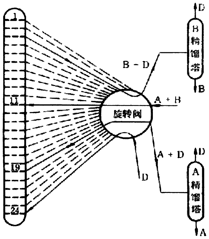
However, due to the different volumes of the pipelines connected to the adsorption column, and the relative position of the circulating pump in the area changes periodically, the flow rate of the circulating pump varies greatly with the area where it is located, making it difficult to control and the pressure fluctuates greatly.

Method used


Image

  • Efficient simulated moving bed equipment and efficient simulated moving bed technology
  • Efficient simulated moving bed equipment and efficient simulated moving bed technology
  • Efficient simulated moving bed equipment and efficient simulated moving bed technology

Examples


Embodiment 1

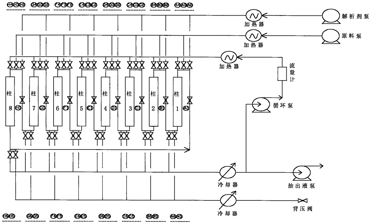
[0048] see figure 2 , taking the adsorption bed composed of 8 adsorption columns as an example.

[0049] A high-efficiency simulated moving bed equipment, including an adsorption bed, a raw material feeding system, a desorbing agent feeding system, a circulation system, an extraction liquid system, a raffinate system, a program-controlled valve group, and an automatic control system; wherein, the adsorption bed Several adsorption columns are divided into adsorption zone, purification zone, desorption zone and buffer zone (it should be pointed out that the present embodiment adopts the adsorption bed comprising adsorption zone, purification zone, desorption zone and buffer zone, but buffer zone is for In the present invention, it is not necessary to choose, but is optional);

[0050] The upper ends of the adsorption columns 1-8 are respectively provided with raw material feed valves A3, B3, C3, D3, E3, F3, G3, H3, and analytical agent feed valves A2, B2, C2, D2, E2, F2, G2, H...

Embodiment 2

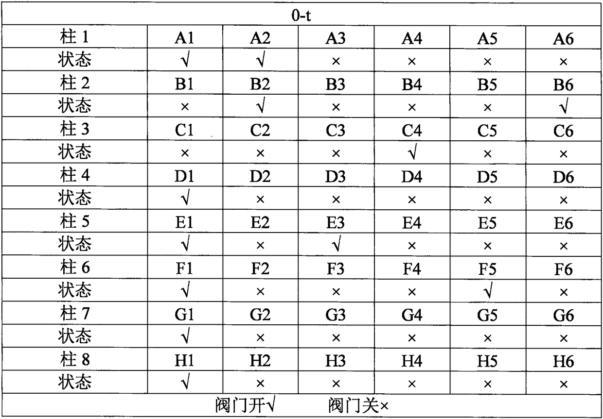
[0069] Adopt the simulated moving bed process of the simulated moving bed equipment of 8 adsorption columns of embodiment 1, control valve switching to change the position of feeding and discharging each time, realize the simulated movement of adsorption zone, purification zone, desorption zone, buffer zone. The specific program control steps are:

[0070] 0-t sequence, open the one-way valve A1 of the adsorption column 1, the desorbent feed valve A2, the desorbent feed valve B2 of the adsorption column 2, the extraction liquid discharge valve B6, and the circulating liquid feed valve C4 of the adsorption column 3 , one-way valve D1 of adsorption column 4, one-way valve E1 of adsorption column 5, raw material feed valve E3, one-way valve F1 of adsorption column 6, raffinate discharge valve F5, one-way valve G1 of adsorption column 7 1. The one-way valve H1 of the adsorption column 8 is opened, and the other valves are closed;

[0071] At this time, the adsorption area is the ...


PUM


Abstract

The invention discloses efficient simulated moving bed equipment and an efficient simulated moving bed technology. The equipment comprises an adsorption bed, a material feeding system, an analysis agent feeding system, a circulating system, a liquid extracting system, a residual liquid extracting system, a program control valve group and an automatic control system. The equipment adopts the program control valve group to replace a traditional multichannel rotary valve to control the cycle transformation of a simulated moving bed, and reduces the cost; the volumes of all pipelines connected with an adsorption column are the same, and the position of a circulating pump is not changed in a region, so that the flow of the circulating pump is not changed, pressure fluctuation is small, and theequipment is simple to control.

Description

technical field [0001] The invention belongs to the technical field of simulated moving bed separation, and in particular relates to a high-efficiency simulated moving bed equipment and a high-efficiency simulated moving bed process. Background technique [0002] The simulated moving bed is a separation device that uses the principle of adsorption for separation operation. As the main representative of continuous chromatography, simulated moving bed technology has the advantages of high production efficiency, less consumption of organic solvents, large mass transfer driving force, and convenient automatic continuous production. It is widely used in petrochemical, food industry and pharmaceutical fields. It is a It is a complex industrial process with many influencing factors, nonlinear, non-equilibrium, non-ideal, multi-degree-of-freedom periodic process. [0003] The simulated moving bed divides the fixed adsorption bed into many sections, which are filled with adsorbents,...

Claims


Application Information

Patent Timeline
IPC IPC(8): B01D15/18
CPCB01D15/1828B01D15/1842B01D2215/023
Inventor 钱震武靖为李俊诚张晶泉菅青娥张晓龙高源邬学霆陈浩庭
Owner INNER MONGOLIA YITAI COAL BASED NEW MATERIALS RES INST CO LTD
Learn More