Self-operated type bevel valve

A bevel valve, self-operated technology, applied in the field of self-operated bevel valve, can solve the problems of constant and easy to change

Pending Publication Date: 2020-02-21
HANGZHOU CHUNJIANG VALVE
View PDF0 Cites 0 Cited by
  • Summary
  • Abstract
  • Description
  • Claims
  • Application Information

AI Technical Summary

Problems solved by technology

[0003] The purpose of the present invention is to solve the problem that the flow rate through the regulating valve is likely to change when the pressure at the inlet or outlet of the regulating valve fluctuates in the prior art pipeline system for conveying liquid, and to provide a self-operated bevel valve that can Automatically stabilizes the differential pressure across the regulator so that the flow through the regulator remains essentially constant

Method used


Image

  • Self-operated type bevel valve

Examples


Embodiment Construction

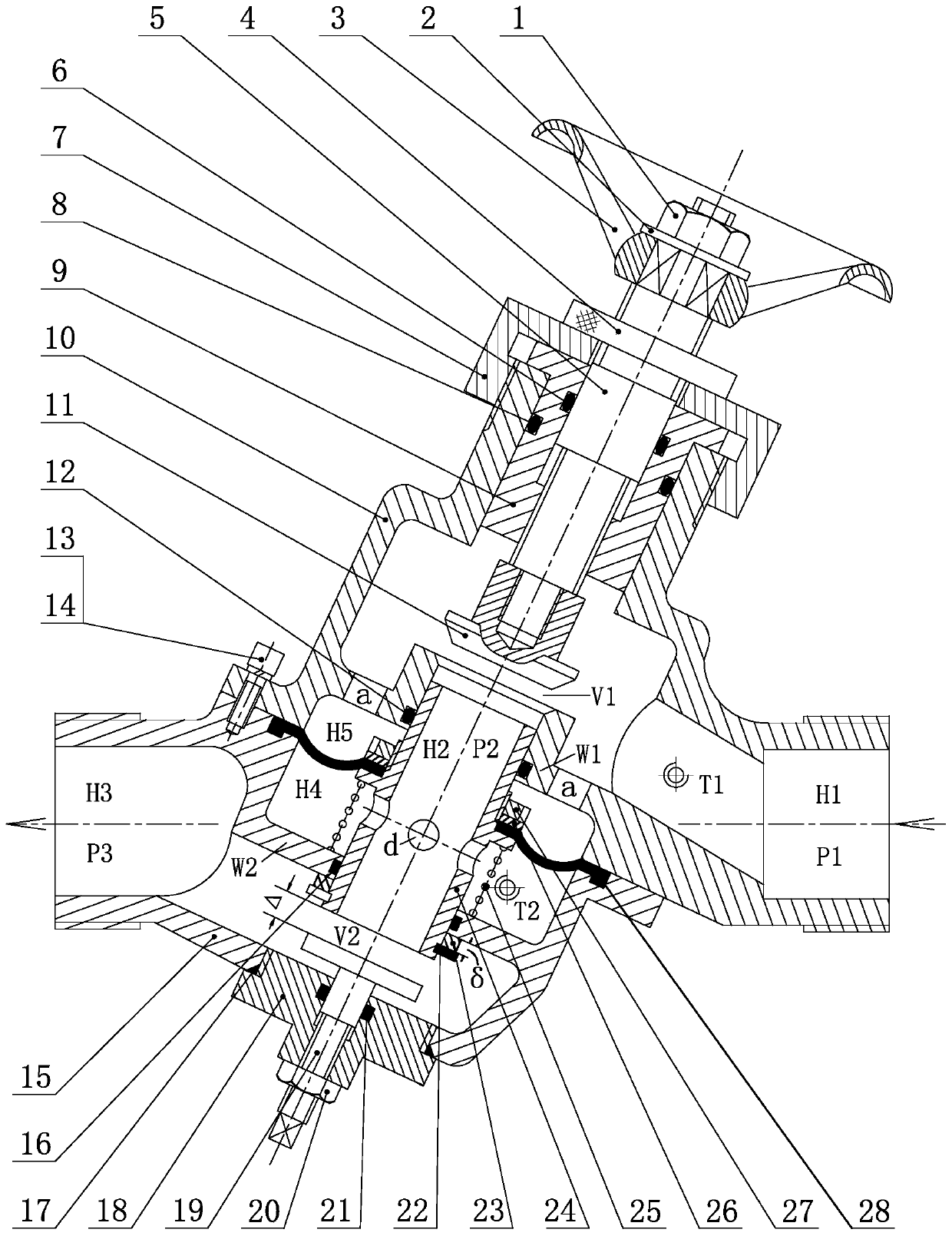
[0015] Through the following examples, combined with the attached figure 1 The specific implementation manners of the present invention will be further described.

[0016] For the longitudinal sectional view of this patent, see figure 1 , including a regulating valve and a constant pressure reducing valve, the regulating valve is set in the cavity of the upper valve body 10, the differential pressure reducing valve is set in the cavity of the lower valve body 15, the lower flange of the upper valve body 10 and the upper flange of the lower valve body 15 Flange is connected as a whole with some auxiliary screws 13, spring washers 14, and the center line of two valve bodies after connecting is on the same axis, and has certain oblique angle with the horizontal axis of inlet and outlet. The lower end of the upper valve body 10 is a flange; the inner hole on the rightward protruding part is a water inlet hole; the upper part is a stepped cylinder with a diameter that is small at ...


PUM


Abstract

The invention discloses a self-operated type bevel valve. The self-operated type bevel valve comprises a regulating valve and a fixed differential reducing valve, wherein the regulating valve is arranged in an upper valve body cavity, the fixed differential reducing valve is arranged in a lower valve body cavity, the fixed differential reducing valve is arranged behind the regulating valve; the upper and lower valve bodies are connected into a whole through fasteners, center lines of the upper and lower valve bodies are on the same axis, and the center lines are provided with certain bevel angles with the horizontal axes of water inlet and outlet holes, the regulating valve comprises a handwheel, a guide sleeve, a valve rod and a valve clack; and the fixed differential reducing valve comprises a sliding valve, a spring, a diaphragm, a lower valve cover, a regulating screw rod, a regulating gasket, a pressing plate and a compression nut. According to the self-operated type bevel valve,when a medium flows, if the pressure of water inlet or outlet chambers fluctuates, the fixed differential reducing valve compensates the pressure at the outlet end of the regulating valve, so that thedifferential pressure at two ends of the regulating valve remains unchanged, and it can be further ensured that the passed flow is constant.

Description

technical field [0001] The invention relates to the technical field of valves, in particular to a self-operated bevel valve. Background technique [0002] In the pipeline system conveying liquid medium, ordinary regulating valves such as ball valves or butterfly valves are usually used to regulate the flow rate, but there is a disadvantage of using such regulating valves alone, that is, when the pressure at the inlet or outlet fluctuates, due to the pressure at both ends of the regulating valve The pressure difference changes, causing the flow through the regulating valve to change, which is undesirable in some occasions. For example, in the air conditioning system, when the amount of hot water or coolant passing through the regulating valve changes, it will cause the controlled The temperature of the environment changes, causing discomfort or wasting energy. This patent is designed to solve the above-mentioned technical deficiencies of ordinary regulating valves. Its creat...

Claims


Application Information

Patent Timeline
Patent Type & Authority Applications(China)
IPC IPC(8): F16K31/385F16K1/00F16K1/32F16K17/30
CPCF16K1/00F16K1/32F16K17/30F16K31/385
Inventor 柴为民陈永新路远航张雪根
Owner HANGZHOU CHUNJIANG VALVE
Why Eureka
Try Eureka