A hydraulic system for regulating the speed of constant pumps in construction machinery

A technology for hydraulic systems and construction machinery, applied in mechanical equipment, fluid pressure actuating devices, servo motors, etc., can solve the problems of hydraulic system overflow energy loss, high production cost, throttling loss, etc., and reduce throttling loss. , strong anti-pollution, reducing the effect of calorific value

Active Publication Date: 2016-08-24
XCMG CONSTR MACHINERY
View PDF9 Cites 0 Cited by
  • Summary
  • Abstract
  • Description
  • Claims
  • Application Information

AI Technical Summary

Problems solved by technology

Adopt throttling speed regulation to make a large amount of hydraulic oil overflow from the throttling port, resulting in energy loss
[0003] In order to solve the overflow energy loss problem of the hydraulic system, the existing solution is to use a variable pump hydraulic system, and control the displacement of the variable pump through the feedback load signal, so that the system flow only meets the system demand, and there is no excess oil overflow
But this scheme has the following disadvantages: 1. In order to adjust the displacement of the variable pump, it is necessary to establish a throttling port in the system to measure the flow demand of the system and adjust the displacement of the variable pump, which causes a large gap between the variable pump port and the load. The pressure difference forms a throttling loss; 2. The hydraulic system of the variable pump must be equipped with a load feedback valve. The variable pump and the load feedback valve have high requirements on the cleanliness of the oil, which reduces the anti-pollution ability of the system; 3. The variable pump And the load feedback valve has complex structure, precise coordination, high production cost and difficult maintenance, which is not conducive to popularization

Method used


Image

  • A hydraulic system for regulating the speed of constant pumps in construction machinery

Examples


Embodiment Construction

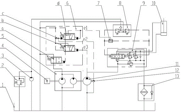
[0013] The present invention will be further described below in conjunction with accompanying drawing.

[0014] Such as figure 1 As shown, the construction machinery constant pump speed regulating hydraulic system of the present invention includes a fuel tank 1, an overflow valve 2, a pilot pump 3, an engine 4, a pump-motor integrated machine 5, and a control valve for controlling the outlet flow of the pump-motor integrated machine 6. Shuttle valve 7, pilot valve 8, multi-way valve 9, actuator, working pump 11 and signal pump 12; engine 4 and working pump 11 are connected through pump-motor integrated machine 5, and signal pump 12 is connected in series with working pump 11 Together and connected to the pump-motor integrated machine 5, the inlet of the working pump 11 and the signal pump 12 is connected to the oil tank 1; the inlet of the pump-motor integrated machine 5 is connected to the oil tank 1, and the outlet is connected to the control valve 6; the oil return port of ...


PUM


Abstract

The invention discloses a fixed-quantity pump speed-regulating hydraulic system for engineering machinery. A pump-motor integrated machine is connected in series between a working pump and an engine. The outlet of the pump-motor integrated machine is connected to a control valve for controlling the outlet flow of the pump-motor integrated machine. , so as to adjust the speed ratio between the working pump and the engine. The control valve is controlled by the pressure at the outlet of the pilot valve, the outlet pressure of the signal pump and the working pump. The greater the speed ratio of the engine, the greater the output flow of the working pump to meet the system demand. When the load pressure changes or the engine speed changes, the control valve adjusts the output flow of the pump-motor integrated machine to ensure that the speed of the working pump remains constant and the system flow is stable, that is, the system flow is not affected by the load and engine speed, reducing throttling loss. It has high energy-saving benefits, adopts quantitative pump and non-load sensitive control valve, has strong anti-pollution ability, simple system components and convenient maintenance.

Description

technical field [0001] The invention relates to a construction machinery hydraulic system, in particular to a construction machinery quantitative pump speed regulation hydraulic system. Background technique [0002] In order to meet market demand, construction machinery (such as loaders) has higher and higher requirements in terms of energy saving, noise reduction, and operating comfort, especially in terms of hydraulic system manipulation. Traditional construction machinery adopts quantitative gear pump hydraulic system, and uses the principle of throttling and speed regulation to control the speed of the actuators of the hydraulic system of construction machinery. The throttling speed regulation makes a large amount of hydraulic oil overflow from the throttling port, resulting in energy loss. [0003] In order to solve the overflow energy loss problem of the hydraulic system, the existing solution is to use the variable pump hydraulic system, and control the displacement ...

Claims


Application Information

Patent Timeline
Patent Type & Authority Patents(China)
IPC IPC(8): F15B11/04
Inventor 范小童任大明刘国伟宋亚莉马鹏鹏
Owner XCMG CONSTR MACHINERY
Why Eureka
Try Eureka