A sinter draft type vertical cooling furnace and a sinter cooling method
A cooling furnace and air extraction technology, which is applied in the sintered ore exhausted vertical cooling furnace and sintered ore cooling, sintered ore cooler and sintered ore cooling field, can solve the problem of low boiler thermal efficiency, difficulty in efficient recovery of sensible heat from sintered ore and the Problems such as utilization, fan power consumption, etc.
- Summary
- Abstract
- Description
- Claims
- Application Information
AI Technical Summary
Problems solved by technology
Method used
Image
Examples
Embodiment 1
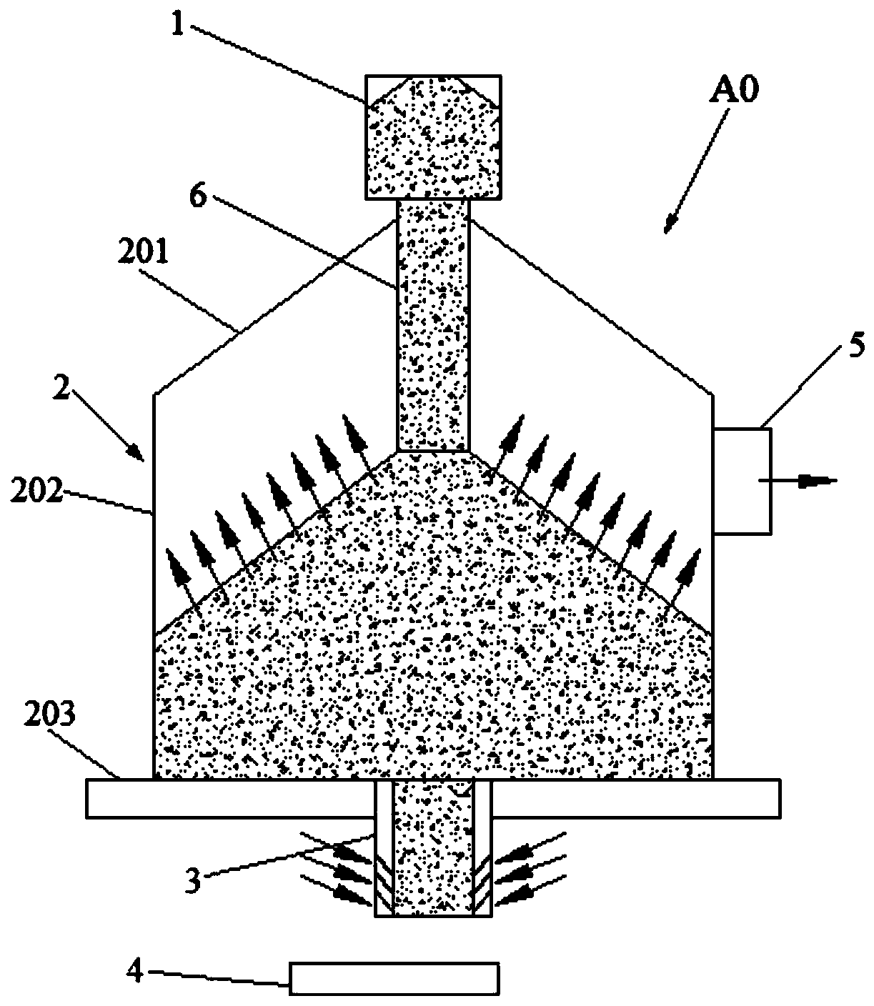
[0115] like figure 1 As shown, a sintered ore extraction type vertical cooling furnace, the vertical cooling furnace A0 includes a silo 1 , a tower body 2 , an air intake and discharge device 3 , and a discharge device 4 . The tower body 2 includes a tower top 201 , a tower wall 202 and a tower bottom 203 . The tower top 201 is provided on top of the tower wall 202 . The tower bottom 203 is arranged at the bottom of the tower wall 202 . The silo 1 is arranged above the tower top 201 and communicates with the inside of the tower body 2 . The air intake and discharge device 3 is arranged below the tower bottom 203 and communicates with the inside of the tower body 2 . The discharge device 4 is arranged below the air intake and discharge device 3 . The upper part of the tower wall 202 is provided with an exhausted hot air outlet 5 . The discharging device 4 is an electro-vibration feeder.
Embodiment 2
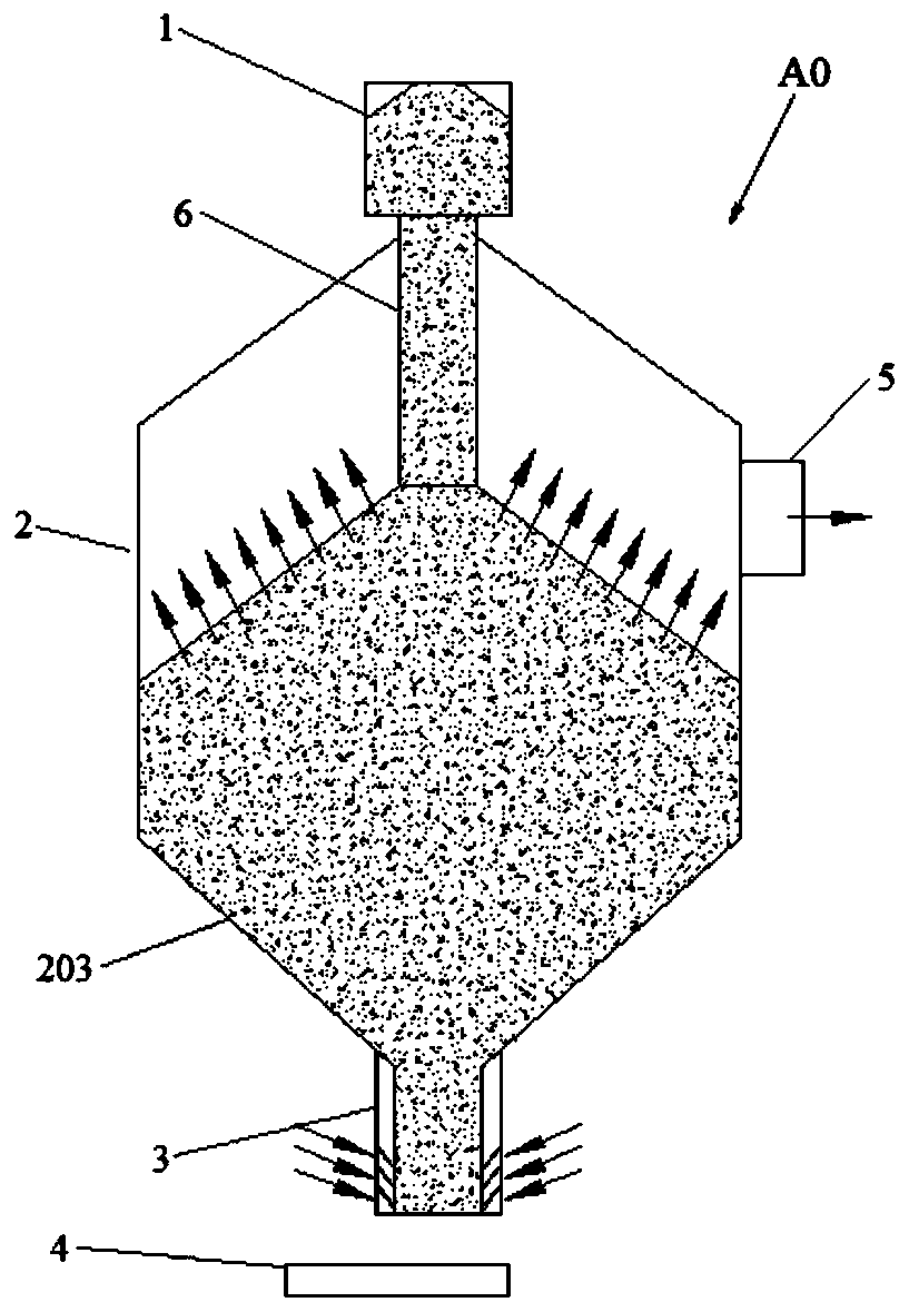
[0117] like figure 2 As shown, Example 1 is repeated, except that the shaft cooling furnace A0 further includes a material sealing distribution pipe 6 . The top of the material seal distribution pipe 6 is connected to the silo 1 , and the material seal distribution pipe 6 extends into the tower body 2 ; the length of the material seal distribution pipe 6 is 55% of the height of the tower body 2 . The bottom of the vertical cooling furnace tower is a cone-bottom structure. The air intake and discharge device 3 is a hollow tubular structure, and the side wall of the air intake and discharge device 3 is a louver structure.
Embodiment 3
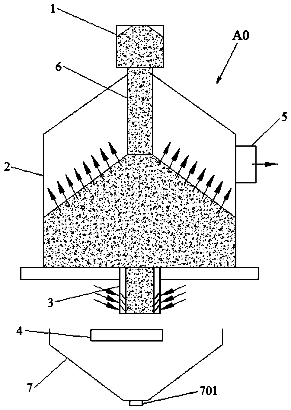
[0119] like image 3As shown, Example 1 is repeated, except that the vertical cooling furnace A0 also includes a material sealing material distribution pipe 6 . The top of material sealing material distribution pipe 6 is connected with feed bin 1, and material sealing material distribution pipe 6 stretches in the tower body 2; The length of material sealing material distribution pipe 6 is 55% of tower body 2 heights. The bottom of the vertical cooling furnace is a flat structure. The air inlet and discharge device 3 is a hollow tubular structure, and the side wall of the air inlet and discharge device 3 is a louver structure. The vertical cooling furnace A0 also includes a discharge chute 7 , and the discharge chute 7 is arranged below the discharge device 4 . The discharge device 4 is a mobile plate discharge device. The moving plate type discharge equipment includes a driving device 401 , a moving plate 402 , a bracket 403 , and a push-pull rod 404 . The support 403 is a...
PUM
| Property | Measurement | Unit |
|---|---|---|
| diameter | aaaaa | aaaaa |
Abstract
Description
Claims
Application Information
 - R&D Engineer
- R&D Manager
- IP Professional
- Industry Leading Data Capabilities
- Powerful AI technology
- Patent DNA Extraction
Browse by: Latest US Patents, China's latest patents, Technical Efficacy Thesaurus, Application Domain, Technology Topic, Popular Technical Reports.
© 2024 PatSnap. All rights reserved.Legal|Privacy policy|Modern Slavery Act Transparency Statement|Sitemap|About US| Contact US: help@patsnap.com


