
Steel ingot teeming runner system

A steel ingot pouring and flowing steel technology, which is applied in the field of flowing steel system, can solve the problems of molten steel composition gradient change, molten steel pollution, and high safety hazards, and achieve the effect of small gradient change of molten steel composition, reasonable pouring time, and low safety hazards

Inactive Publication Date: 2015-03-11
TAIYUAN HEAVY IND
View PDF9 Cites 8 Cited by
  • Summary
  • Abstract
  • Description
  • Claims
  • Application Information

AI Technical Summary

Problems solved by technology

[0003] It can be seen from the above that according to the existing pouring system, the pouring time is too long, technical considerations, molten steel cooling is large, the composition gradient of molten steel changes, the quality of steel ingots is unstable, production considerations are difficult to organize, and safety hazards are high;
[0004] In addition, the central brick 6' for pouring is hexagonal, with sharp edges inside, and the refractory material is easy to fall off when the molten steel flows through, causing molten steel pollution; there is no buffer section for the molten steel flow rate, the molten steel punching process is too fast, and there is slag curling in the production steel ingot and secondary shrinkage holes and other quality hazards; flat buckles are used between the tail brick and the bottom brick of the mold, and there is often misalignment between the two, resulting in different rise heights of the 6 steel ingots in the plate during the punching process, resulting in some steel ingots scrapped

Method used


Image

  • Steel ingot teeming runner system
  • Steel ingot teeming runner system
  • Steel ingot teeming runner system

Examples


Embodiment Construction

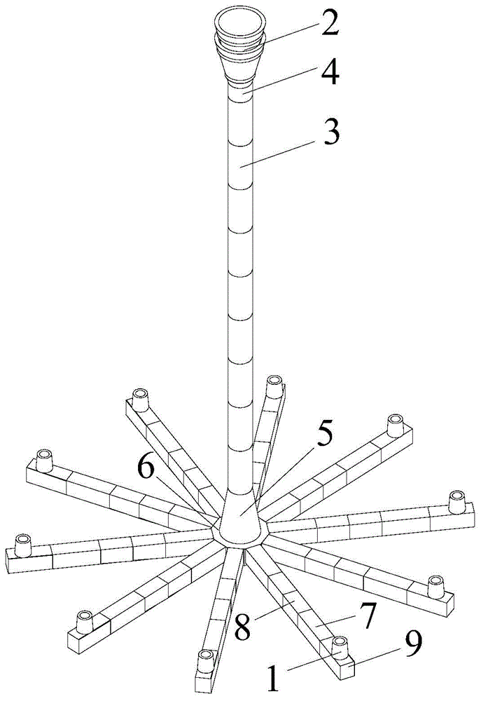
[0032] Figure 1A Shown is a combination schematic diagram of a steel ingot pouring flow steel system according to an embodiment of the present invention; Figure 1B shown as Figure 1A The schematic diagram of the main view; Figure 1C shown along Figure 1B A cross-sectional view of line A-A in. Such as Figure 1A to Figure 1C As shown, the steel ingot pouring flow steel system provided by an embodiment of the present invention includes funnel brick 2, cast pipe brick 3, first type central brick 4, joint brick 5, second type central brick 6, first type flow steel brick 7 , the second type flow steel brick 8, flow steel tail brick 9 and mold bottom brick 1.

[0033] Such as Figure 1A to Figure 1C As shown, flow steel flows through the vertical cast pipe 10 arranged vertically to the horizontal cast pipe 20 arranged horizontally below. The vertical casting pipe 10 is made up of two funnel bricks 2, a plurality of casting pipe bricks 3, a first type center brick 4 and a...


PUM


Abstract

The invention provides a steel ingot teeming runner system which comprises vertical cast tube, horizontal cast tubes, mold bottom bricks and a second kind center brick for connecting the vertical cast tube and the horizontal cast tubes, wherein the vertical cast tubes comprise funneled bricks, a plurality of cast tube bricks arranged below the funneled bricks, a first kind center brick connected between the funneled brick and the cast tube bricks and a joint brick for connecting the cast tube bricks and the second kind center brick; and the horizontal cast tubes comprise runner bricks and end runner bricks, the runner bricks are connected with the second kind center brick, and the end runner bricks are connected with tail ends of the runner bricks.

Description

technical field [0001] The invention relates to a flow steel system for pouring steel ingots. Background technique [0002] In the existing steel ingot smelting technology, 30tEBT+120tLFV is mainly used for smelting. Figure 11 and Figure 12 Shown is the stereogram and front view of the existing flow steel system. Such as Figure 11 and Figure 12 As shown, the existing flow steel system produces six steel ingots per tray. The flow steel system includes funnel brick 2', cast pipe brick 1', 3', center brick 6', flow steel brick 8', 7', flow steel tail brick 9' and mold bottom brick 10'. The existing flow steel system casts 3 trays of 16 ingots per furnace (6 in the first tray, 6 in the second tray, and 4 ingots in the third tray), and the pouring time is about 50 minutes (about 17 minutes for each tray), using a funnel Brick 2', cast pipe brick 1', 3', center brick 6', flowing steel brick 8', flowing steel tail brick 9' and mold bottom brick 10' are produced in a complet...

Claims


Application Information

Patent Timeline
Patent Type & Authority Applications(China)
IPC IPC(8): B22D7/06
CPCB22D7/06
Inventor 陈培红许益华
Owner TAIYUAN HEAVY IND
Learn More