
CT self-powered switchgear testing device and system thereof

A detection device, switchgear technology, applied in the direction of measuring device, measuring device casing, circuit breaker testing, etc., can solve the problems of accelerated dynamic and static contact contact oxidation, high temperature in the contact area, high voltage, etc. Achieve accurate measurement results, strong anti-interference ability, and accurate measurement

Pending Publication Date: 2019-02-26
SHANGHAI MUNICIPAL ELECTRIC POWER CO
View PDF9 Cites 2 Cited by
  • Summary
  • Abstract
  • Description
  • Claims
  • Application Information

AI Technical Summary

Problems solved by technology

In the high-voltage circuit breaker handcart structure, there is a certain contact resistance between the moving contact and the static contact. If the contact resistance is too large, a large part of the electric energy will be lost in the form of heat radiation, making the contact area The temperature rises, thereby accelerating the oxidation of the contact between the dynamic and static contacts
The result of oxidation will lead to a further increase in the contact resistance value, and then the problem of excessive temperature in the contact area will fall into a vicious circle, and even the contact will be damaged by arcing.
Traditional infrared, temperature-indicating wax sheets and other temperature measurement methods have long cycles, complex construction, low efficiency, and inconvenient management. When a fault occurs, it will take a lot of manpower to physically check and re-lay
However, in certain occasions, the monitoring points are scattered, the environment is closed or there is high voltage, and many temperature measurement methods cannot realize the measurement work.

Method used


Image

  • CT self-powered switchgear testing device and system thereof
  • CT self-powered switchgear testing device and system thereof
  • CT self-powered switchgear testing device and system thereof

Examples


Embodiment Construction

[0044] The present invention will be further elaborated below by describing a preferred specific embodiment in detail in conjunction with the accompanying drawings.

[0045] The internal insulation defect or deterioration of the high-voltage switchgear and the poor contact of the conductive connection will affect the safe and reliable operation of the switchgear. The switchgear usually uses air as the insulating medium. When there is a discharge phenomenon in the switchgear, the oxygen with two oxygen atoms in the air will be converted into ozone gas with three oxygen atoms. Therefore, the present invention opens the cabinet by detecting or monitoring The internal ozone gas content or concentration changes to indirectly monitor whether there is a discharge phenomenon in the switch, so as to evaluate the insulation state in the switch cabinet. And ozone only has a maximum absorption coefficient for ultraviolet rays with a wavelength of 253.7nm, so the principle of ultraviolet s...


PUM


Abstract

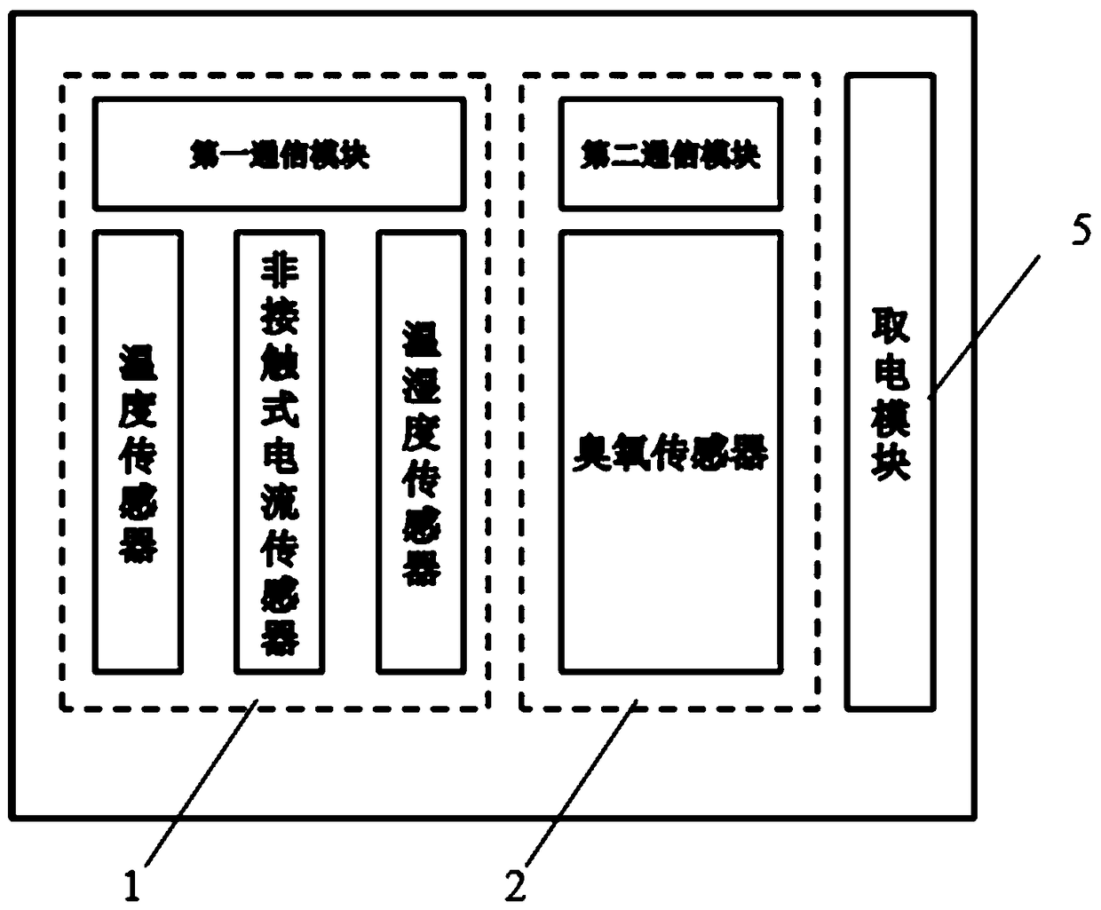
A CT self-powered switchgear testing device comprises the components of a temperature / humidity / current measuring module which measures the temperature and current of a switch plum blossom contact andenvironment temperature humidity data in the switchgear; an ozone measuring module which measures ozone concentration data in the switchgear; a first communication module; a second communication module; a powering module which automatically senses energy from high-voltage electrified equipment for supplying power to the ozone measuring module, the first communication module and the second communication module; and a metal annular band on which the temperature / humidity / current measuring module, the ozone measuring module and the powering module are mounted, wherein two ends of the metal annularband are connected through buckles, thereby forming a closed loop which is snapped with the edge of the switch plum blossom contact. The CT self-powered switchgear testing device has an advantages ofaccurate measurement for the temperature and the current of the switch contact, an environment temperature, an environment humidity and an ozone content in switch operation, thereby realizing evaluation to an insulating state.

Description

technical field [0001] The invention relates to the technical field of power system detection, in particular to a detection device and system for a CT self-feeding switch cabinet. Background technique [0002] At present, the handcart switchgear is widely used in the power supply system. In the high-voltage circuit breaker handcart structure, there is a certain contact resistance between the moving contact and the static contact. If the contact resistance is too large, a large part of the electric energy will be lost in the form of heat radiation, making the contact area The temperature rises, thereby accelerating the oxidation of the contact between the dynamic and static contacts. The result of oxidation will further increase the contact resistance value, and then the problem of excessive temperature in the contact area will fall into a vicious circle, and even the contact will be burned by arcing. Traditional temperature measurement methods such as infrared and temperat...

Claims


Application Information

Patent Timeline
Patent Type & Authority Applications(China)
IPC IPC(8): G01R31/327G01R1/04G01D21/02
CPCG01D21/02G01R1/04G01R31/3271G01R31/3274G01R31/3275
Inventor 万轶伦谢邦鹏吴舒鋆汤蕾洪俊聂鹏晨许晓波周毅章冲茅竹韧曹炀盛杰孙博袁浩悦张颖达袁伟刚
Owner SHANGHAI MUNICIPAL ELECTRIC POWER CO
Learn More