An Asymmetric Spatial Heterodyne Spectrometer Based on Improved Koster Prism

An improved spatial heterodyne technology, which is applied in the field of optical structure design of asymmetric spatial heterodyne spectrometers, can solve the problems of small optical path difference offset, achieve high stability, low difficulty in installation and adjustment, and improve sensitivity Effect

Active Publication Date: 2021-01-05
INST OF OPTICS & ELECTRONICS - CHINESE ACAD OF SCI
View PDF5 Cites 0 Cited by
  • Summary
  • Abstract
  • Description
  • Claims
  • Application Information

AI Technical Summary

Problems solved by technology

[0006] The technical problem to be solved by the present invention is: The problem of the small offset of the optical path difference of the asymmetric spatial heterodyne spectrometer with the prism as the beam splitter is proposed based on the improved Prism based asymmetric spatial heterodyne spectrometer

Method used


Image

  • An Asymmetric Spatial Heterodyne Spectrometer Based on Improved Koster Prism

Examples


Embodiment 1

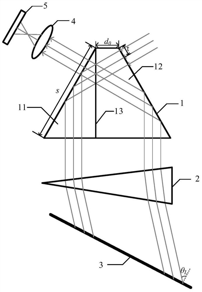
[0023] Embodiment 1 of the present invention is a single-arm offset of 21mm, and the minimum resolvable wavenumber difference is 0.6615cm -1 , a spectral resolution of 23994, a quasi-common channel asymmetric spatial heterodyne spectrometer with a free spectral range of 630-646nm. like figure 1 As shown, the present invention is based on an improved Prism-based asymmetric spatial heterodyne spectrometers include: Improved Prism 1; field of view expanding prism 2; blazed grating 3; imaging lens 4; detector 5. Among them, the apex angle of the field-of-view expansion prism 2 is 9.0562°; the Littrow angle of the blazed grating 3 is 10.7°, and the Littrow wavelength is 630nm; the imaging ratio of the imaging lens is 1:1; the detector size is 1248×1248, and the pixel size is 16 μm .

[0024] The collimated signal light incident vertically along the optical axis is improved After the prism 1 is divided into two beams, they are perpendicular to the modified beam with differen...

Embodiment 2

[0030] Embodiment 2 of the present invention is a single-arm offset of 35mm, and the minimum resolvable wavenumber difference is 0.3544cm -1 , the spectral resolution is 36982, the free spectral range is 763 ~ 780nm quasi-common path asymmetric spatial heterodyne spectrometer. like figure 1 As shown, the present invention is based on an improved Prism-based asymmetric spatial heterodyne spectrometers include: Improved Prism 1; field of view expanding prism 2; blazed grating 3; imaging lens 4; detector 5. Among them, the apex angle of the field of view expansion prism 2 is 11.2174°; the Littrow angle of the blazed grating 3 is 13.2323°, and the Littrow wavelength is 763nm; the imaging ratio of the imaging lens is 1:1; the detector size is 2048×2048, and the pixel size is 15 μm .

[0031] The collimated signal light incident vertically along the optical axis is improved After the prism 1 is divided into two beams, they are perpendicular to the asymmetric beam with differ...


PUM


Abstract

The invention discloses an asymmetric spatial heterodyne spectrometer based on an improved Koster prism. The asymmetric spatial heterodyne spectrometer comprises an improved Koster prism, a view fieldexpanding prism, a blazed grating, an imaging lens, and a detector. The improved Koster prism is formed by gluing of a rectangular prism and a rectangular trapezoid lens; and the gluing surface serves as a light-split surface. Incident collimating signal light is split into two beams by the light-split surface of the improved Koster prism and then the split light beams are emitted from a lower bottom surface perpendicular to the improved Koster prism at different optical paths; the two emitted light beams are refracted by the view field expanding prism and the refracted beams are diffracted by the grating; the diffracted beams enter the improved Koster prism again and the interference is formed at the exit surface; and the imaging lens images an interference fringe on the detector. According to the asymmetric spatial heterodyne spectrometer, while the design of the quasi-co-directional structure is ensured, the e optical path difference offset of the two interference optical paths canbe increased effectively, so that the Doppler velocity measuring sensitivity of the instrument is improved.

Description

technical field [0001] The invention belongs to the design field of spectroscopic instruments and interference instruments, and relates to an improved Optical structure design of a prism-based asymmetric spatial heterodyne spectrometer. Background technique [0002] In 2006, the U.S. Naval Laboratory first proposed a new Doppler passive detection technology, Doppler Asymmetric Spatial Heterodyne Spectroscopy (DASH) technology. Based on the spatial heterodyne spectroscopy (SHS) technique, this technology increases the distance from one arm grating to the beam splitter. Therefore, on the one hand, DASH technology inherits the advantages of SHS technology such as large throughput, large field of view, small size, small volume, and light weight, and on the other hand, it has the functions of ultra-high spectral resolution and high-sensitivity interferometer, which can At the same time, high-resolution spectral detection and high-sensitivity Doppler frequency shift detection o...

Claims


Application Information

Patent Timeline
Patent Type & Authority Patents(China)
IPC IPC(8): G01J3/28G01J3/02G01J3/12
CPCG01J3/0205G01J3/12G01J3/28G01J2003/1208
Inventor 方亮况银丽程欣彭翔张辉刘恩海
Owner INST OF OPTICS & ELECTRONICS - CHINESE ACAD OF SCI
Why Eureka
Try Eureka