A ceramic inner hole grinding device
A technology of inner holes and ceramics, which is applied in the direction of grinding machines, grinding/polishing equipment, and parts of grinding machine tools, etc. It can solve problems such as difficult hole chamfering and inability to adjust and adapt
- Summary
- Abstract
- Description
- Claims
- Application Information
AI Technical Summary
Problems solved by technology
Method used
Image

Examples
specific Embodiment approach 1
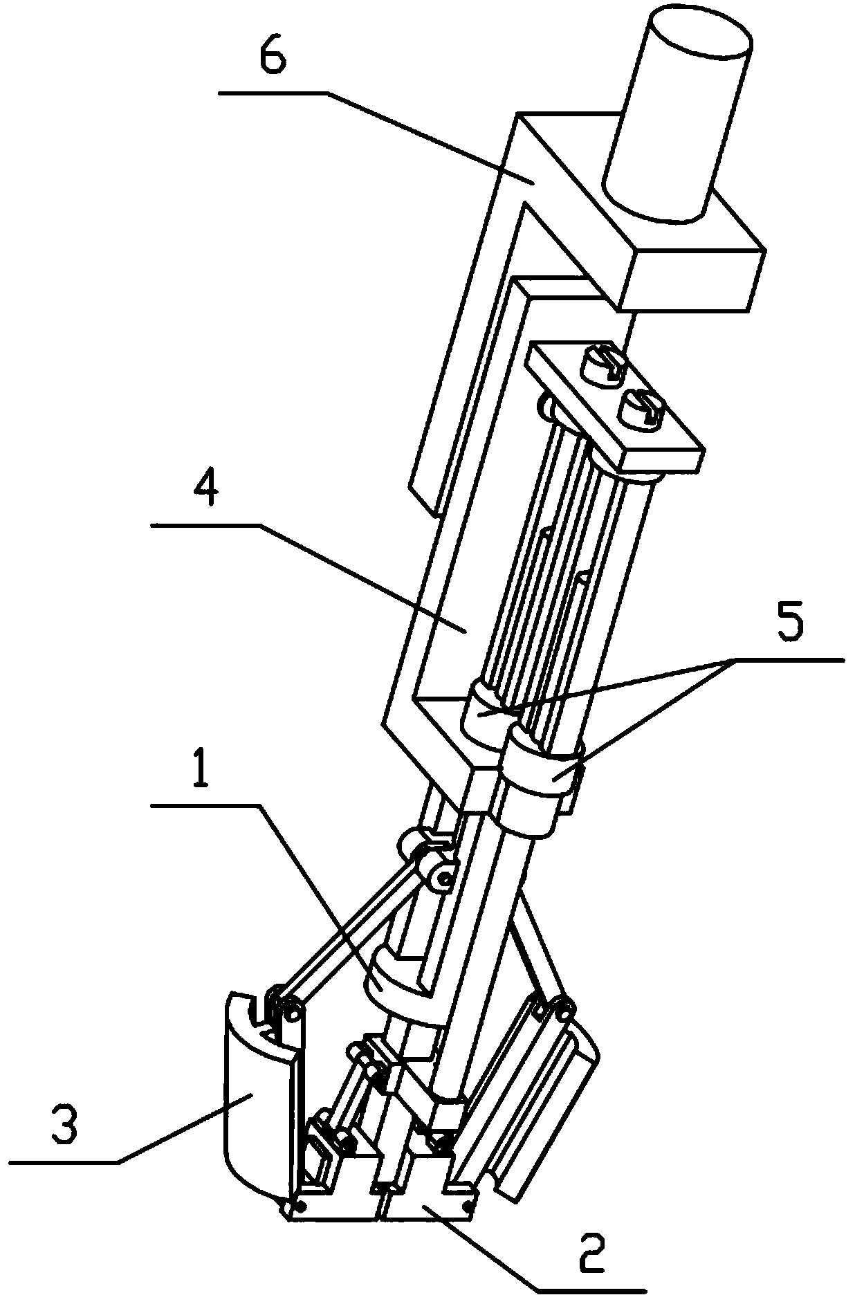
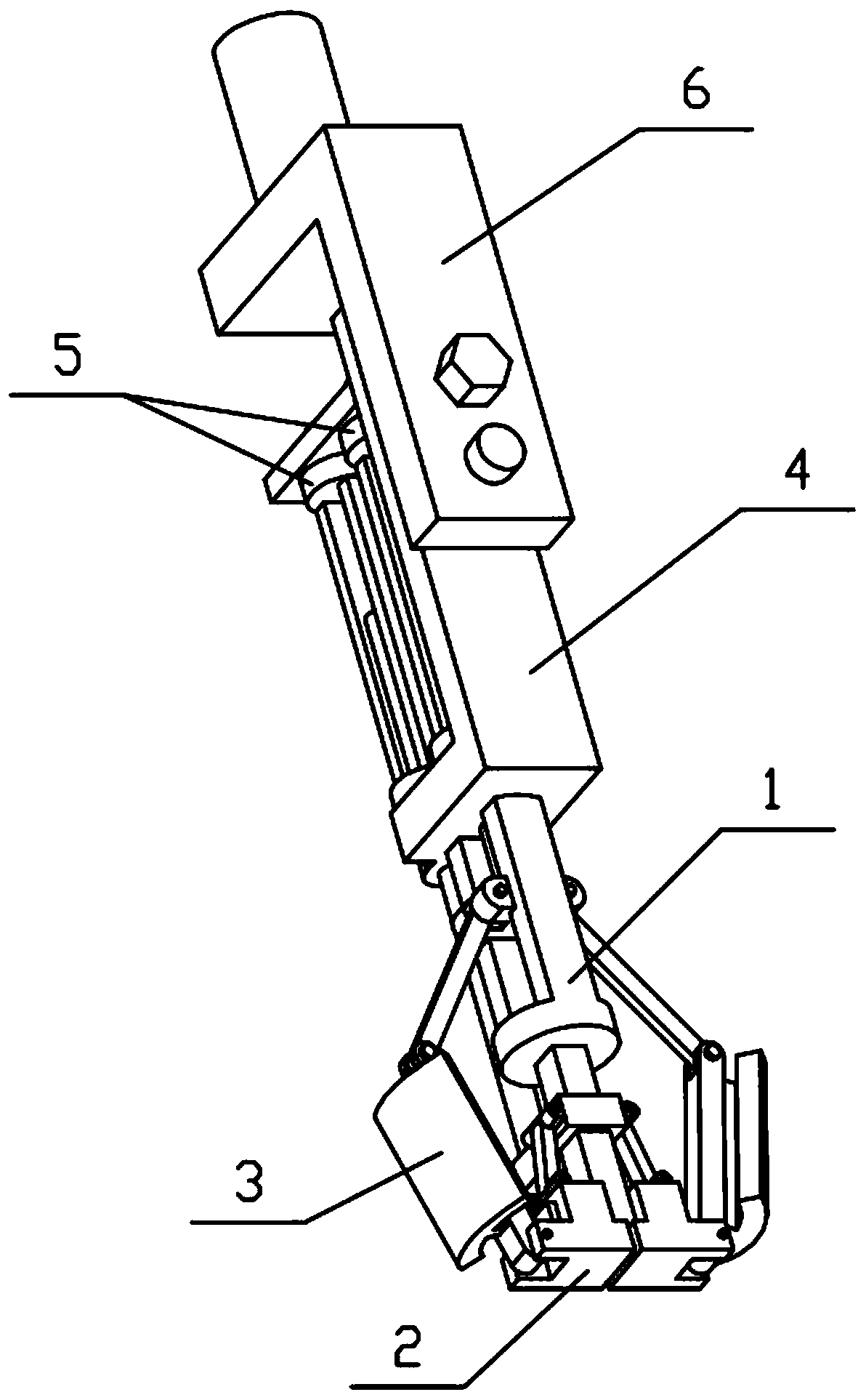
[0032] Combine below Figure 1-13 To illustrate this embodiment, the present invention relates to a ceramic processing tool, more specifically, a ceramic inner hole grinding device, which includes a frame body 1, a bottom telescopic frame 2, a grinding mechanism 3, an upper frame 4, a rotating adjustment member 5 and Connecting assembly 6, the inclination of the two arc-shaped grinding sheets 3-4 in the present invention can be adjusted, so as to facilitate the chamfering of the ceramic inner hole; 3-4 can be adjusted to the level; and the distance between the upper end and the lower end of the two arc-shaped grinding pieces 3-4 can be adjusted, so as to achieve grinding and chamfering of ceramic inner holes with different diameters.
[0033] The middle end and the left and right ends of the bottom telescopic frame 2 are all slidably connected with the frame body 1, the middle end of the grinding mechanism 3 is slidably connected with the frame body 1, and the left and right e...
specific Embodiment approach 2
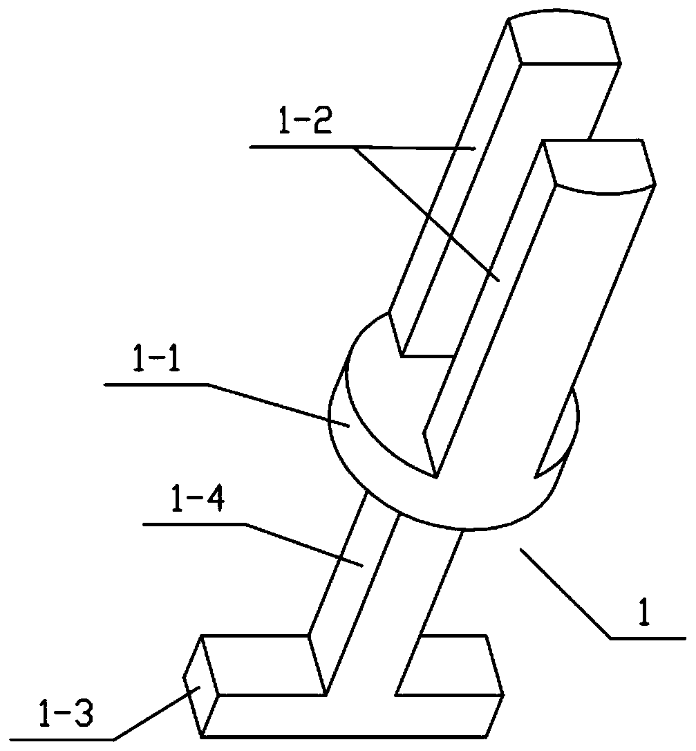
[0035] Combine below Figure 1-13Describe this embodiment, this embodiment will further explain the first embodiment, the frame body 1 includes a circular seat 1-1, an arcuate rod 1-2, a horizontal column 1-3 and a vertical column 1-4, and the circular seat 1- 1. The front and rear ends of the upper end are fixedly connected with an arcuate rod 1-2, the lower end of the round seat 1-1 is fixedly connected with a vertical column 1-4, and the lower end of the vertical column 1-4 is fixedly connected with the upper end of the horizontal column 1-3 centre position.
specific Embodiment approach 3
[0037] Combine below Figure 1-13 Describe this embodiment, this embodiment will further explain the second embodiment, the bottom telescopic frame 2 includes a vertical sliding sleeve 2-1, an equal arm I2-2, a horizontal sliding sleeve 2-3, and a bottom sliding block 2-4 , front extension column 2-5 and threaded rod 12-6, vertical sliding sleeve 2-1 is slidably connected on the vertical column 1-4, and the front end of vertical sliding sleeve 2-1 is fixedly connected with front extension column 2-5, and front extension The upper end of the column 2-5 is fixedly connected with a threaded rod I2-6, the left and right ends of the vertical sliding sleeve 2-1 are hingedly connected with an equal arm I2-2, and the bottom slider 2-4 is provided with two, two The upper end of the bottom slider 2-4 is fixedly connected with a horizontal sliding sleeve 2-3, and the two horizontal sliding sleeves 2-3 are slidably connected to the left and right ends of the horizontal column 1-3 respecti...
PUM
 Abstract
Description
Claims
Application Information
 - R&D
- Intellectual Property
- Life Sciences
- Materials
- Tech Scout
- Unparalleled Data Quality
- Higher Quality Content
- 60% Fewer Hallucinations
Browse by: Latest US Patents, China's latest patents, Technical Efficacy Thesaurus, Application Domain, Technology Topic, Popular Technical Reports.
© 2025 PatSnap. All rights reserved.Legal|Privacy policy|Modern Slavery Act Transparency Statement|Sitemap|About US| Contact US: help@patsnap.com