
Quasi-static test method of dynamic index of gravity unloading device

A technology of dynamic indicators and testing methods, applied in the field of aerospace, can solve problems such as large differences in gravity unloading equipment capacity indicators, adverse effects of funds, equipment developers and development cycles, and technical complexity

Active Publication Date: 2019-02-19
HARBIN INST OF TECH
View PDF4 Cites 2 Cited by
  • Summary
  • Abstract
  • Description
  • Claims
  • Application Information

AI Technical Summary

Problems solved by technology

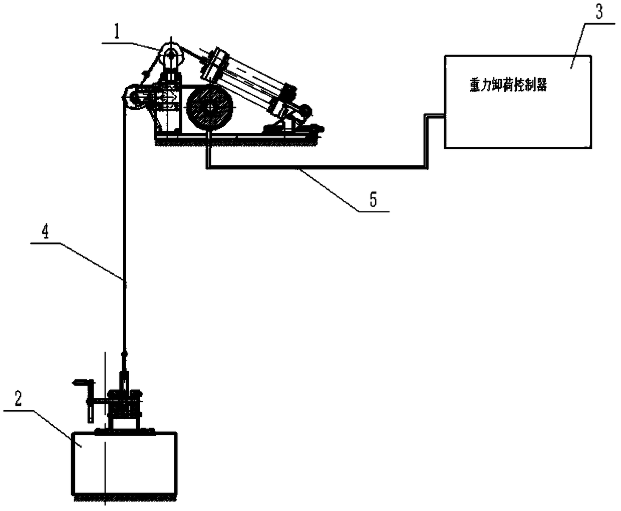
In the traditional test method, the quantitative test of this index needs to make special test equipment to generate the actual input signal d, namely figure 1 The medium load is a set of electromechanical equipment with a hoisting mechanism and an independent control system. The technology is complex and requires a separate operator to operate, and the development cycle is relatively long
In addition, the capacity indicators of different series of gravity unloading equipment are very different. In order to meet their testing needs, they often need to have supporting testing equipment, which has a negative impact on funds, equipment developers and development cycles.

Method used


Image

  • Quasi-static test method of dynamic index of gravity unloading device
  • Quasi-static test method of dynamic index of gravity unloading device
  • Quasi-static test method of dynamic index of gravity unloading device

Examples


specific Embodiment approach 1

[0055] Specific implementation mode one: this implementation mode provides a kind of static test method for the dynamic index standard of SISO system, and the concrete implementation steps of described method are as follows:

[0056] Step 1. Establish the dynamic state space mathematical model of the mechanical part of the gravity unloading equipment:

[0057]

[0058] In the formula, y can be but not limited to the tension on the wire rope, u is the control signal of the motor, and d is the input disturbance item (or command signal) when evaluating dynamic indicators such as the speed or acceleration of the load. X is the state variable, A, B u ,B d ,C,D u ,D d is the system matrix of the corresponding dimension.

[0059] For example, the state space model of the mechanical part of a gravity unloading system is

[0060]

[0061] C = [3000 0 -3000 0], D u =D d =0.

[0062] Calculate the transfer function matrix from u to y and from d to y according to the dynamic...

specific Embodiment approach 2

[0120] Specific implementation mode two: this implementation mode provides a dynamic index standard static test method for a MIMO system, and the specific implementation steps of the method are as follows:

[0121] When the mechanical equipment has multiple controllable input quantities, it can be considered to reasonably distribute the virtual signal to reduce the P u The delay effect of a non-minimum phase zero in one of the channels can also be evaluated simultaneously using multiple outputs when the following conditions are met.

[0122] The conformance conditions under which multiple output characteristics can be evaluated simultaneously are: satisfies formula (5) and Make P u (s)H(s)=P d (s)S(s) has a solution.

[0123] Get an appropriate number of outputs (1 or more than 1 can be), this test method can be implemented under the above conditions, other steps are the same as the specific implementation mode 1, and wherein step 3 is changed as follows:

[0124] Calcu...


PUM


Abstract

The invention discloses a quasi-static test method of a dynamic index of a gravity unloading device. The method includes the following steps of firstly, calculating a transfer function matrix; secondly, dividing the structure of a gravity unloading control system, and reserving a signal port w; thirdly, calculating H(s); fourthly, discretizing the H(2) to obtain H(z), compiling a program, obtaining the H(z), and assigning the H(z) to uc; fifthly, compiling a test signal generator with an input function di; sixthly, connecting with the gravity unloading device for testing; seventhly, setting vto be equal to 0, setting a parameter tensile force instruction r to be working tensile force, and making the gravity unloading device enter a force constant working state; eighthly, sending out an instruction and exciting the system to operate; ninthly, processing data to obtain a to-be-estimated system performance index; tenthly, evaluating errors. No special movement generating device is used,and the dynamic index can be tested under the quasi-static conditions.

Description

technical field [0001] The invention belongs to the field of aerospace technology, and relates to a testing method for a microgravity simulation experiment platform, in particular to a quasi-static testing method for dynamic indicators of gravity unloading equipment. Background technique [0002] In order to reduce the development cost of aerospace equipment, improve reliability, and shorten the R&D cycle, it is necessary to check the entire life of equipment such as equipment functions, performance indicators, work reliability, operating procedures, failure modes, and countermeasures on the ground during the R&D process or before launch. All problems that may be faced during the cycle are verified as efficiently as possible to help designers find design defects as early as possible, modify and verify them, and help operators and managers formulate reasonable operating procedures and reliable emergency response measures , familiar with the operation process. However, since ...

Claims


Application Information

Patent Timeline
IPC IPC(8): B64G7/00
CPCB64G7/00
Inventor 卢鸿谦丁戍辰尹航班晓军黄显林樊世超杨晓宁
Owner HARBIN INST OF TECH
Learn More